sh030106u.pdf - 第189页
5. PARAMETE RS 5 - 44 No. Sym bol Name and function Initial value [unit] Setting range PD11 *DIF Input fi lter setti ng Select t he input filt er. Refer to t he "Name and function" c olumn. Setting digit Explan…
5. PARAMETERS
5 - 43
No. Symbol Name and function
Initial
value
[unit]
Setting
range
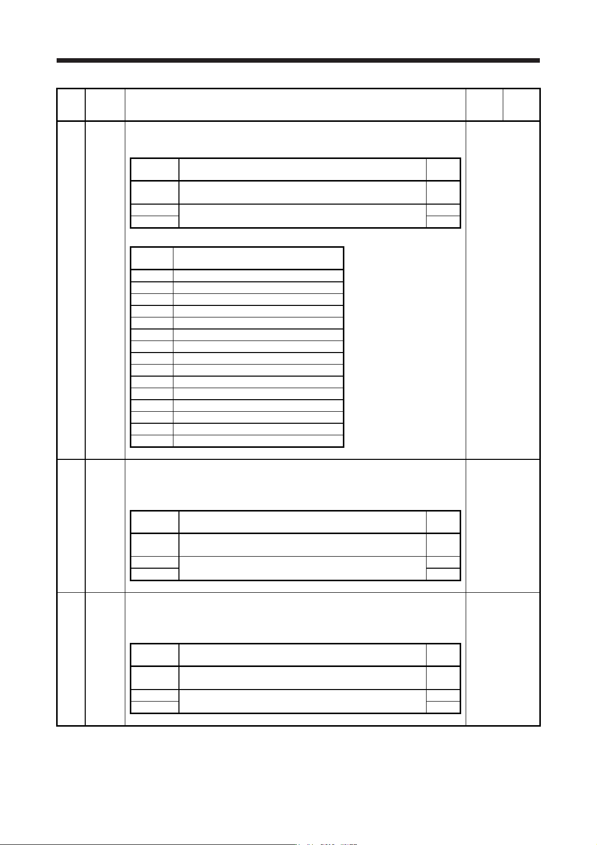
PD07 *DO1 Output device selection 1
You can assign any output device to the CN3-13 pin. MBR (Electromagnetic brake interlock)
is assigned as the initial value.
Refer to the
"Name and
function" column.
Setting
digit
Explanation
Initial
value
_ _ x x Device selection
Refer to table 5.8 for settings.
05h
_ x _ _ For manufacturer setting 0h
x _ _ _ 0h
Table 5.8 Selectable output devices
Setting
value
Output device
_ _ 0 0 Always off
_ _ 0 2 RD (Ready)
_ _ 0 3 ALM (Malfunction)
_ _ 0 4 INP (In-position)
_ _ 0 5 MBR (Electromagnetic brake interlock)
_ _ 0 6 DB (Dynamic brake interlock)
_ _ 0 7 TLC (Limiting torque)
_ _ 0 8 WNG (Warning)
_ _ 0 9 BWNG (Battery warning)
_ _ 0 A SA (Speed reached)
_ _ 0 C ZSP (Zero speed detection)
_ _ 0 F CDPS (Variable gain selection)
_ _ 1 0 CLDS (During fully closed loop control)
_ _ 1 1 ABSV (Absolute position undetermined)
_ _ 1 7 MTTR (During tough drive)
PD08 *DO2 Output device selection 2
You can assign any output device to the CN3-9 pin. INP (In-position) is assigned as the initial
value.
The devices that can be assigned and the setting method are the same as in [Pr. PD07].
Refer to the
"Name and
function" column.
Setting
digit
Explanation
Initial
value
_ _ x x Device selection
Refer to table 5.8 in [Pr. PD07] for settings.
04h
_ x _ _ For manufacturer setting 0h
x _ _ _ 0h
PD09 *DO3 Output device selection 3
You can assign any output device to the CN3-15 pin. ALM (Malfunction) is assigned as the
initial value.
The devices that can be assigned and the setting method are the same as in [Pr. PD07].
Refer to the
"Name and
function" column.
Setting
digit
Explanation
Initial
value
_ _ x x Device selection
Refer to table 5.8 in [Pr. PD07] for settings.
03h
_ x _ _ For manufacturer setting 0h
x _ _ _ 0h
5. PARAMETERS
5 - 44
No. Symbol Name and function
Initial
value
[unit]
Setting
range
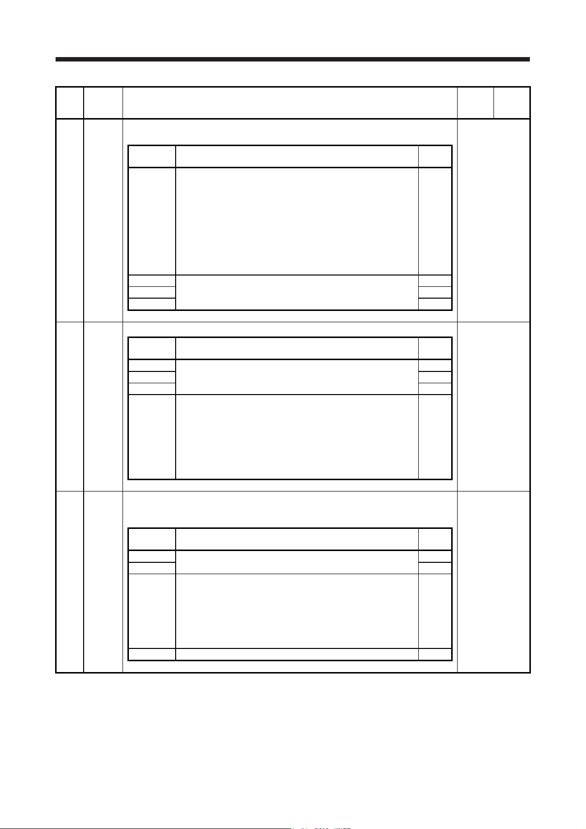
PD11 *DIF Input filter setting
Select the input filter.
Refer to the
"Name and
function" column.
Setting
digit
Explanation
Initial
value
_ _ _ x Input signal filter selection
Refer to the servo system controller instruction manual for the
setting.
If external input signal causes chattering due to noise, etc., input
filter is used to suppress it.
0: None
1: 0.888 [ms]
2: 1.777 [ms]
3: 2.666 [ms]
4: 3.555 [ms]
4h
_ _ x _ For manufacturer setting 0h
_ x _ _ 0h
x _ _ _ 0h
PD12 *DOP1 Function selection D-1
Refer to the
"Name and
function" column.
Setting
digit
Explanation
Initial
value
_ _ _ x For manufacturer setting 0h
_ _ x _ 0h
_ x _ _ 0h
x _ _ _
Servo motor or linear servo motor thermistor enabled/disabled
selection
0: Enabled
1: Disabled
For servo motors or linear servo motor without thermistor, the
setting will be disabled.
This parameter setting is used with servo amplifier with software
version A5 or later.
0h
PD13 *DOP2 Function selection D-2
Select the INP (In-position) on condition.
This parameter is supported with software version B4 or later.
Refer to the
"Name and
function" column.
Setting
digit
Explanation
Initial
value
_ _ _ x For manufacturer setting 0h
_ _ x _ 0h
_ x _ _ INP (In-position) on condition selection
Select a condition that INP (In-position) is turned on.
0: Droop pulses are within the in-position range.
1: The command pulse frequency is 0, and droop pulses are within
the in-position range.
When the position command is not inputted for about 1 ms, the
command pulse frequency is decided as 0.
0h
x _ _ _ For manufacturer setting 0h
5. PARAMETERS
5 - 45
No. Symbol Name and function
Initial
value
[unit]
Setting
range
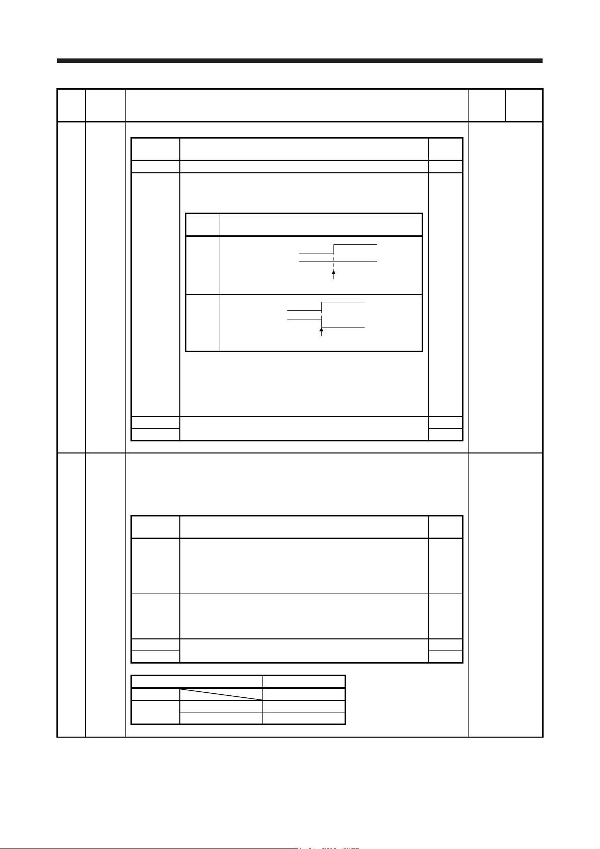
PD14 *DOP3 Function selection D-3
Refer to the
"Name and
function" column.
Setting
digit
Explanation
Initial
value
_ _ _ x For manufacturer setting 0h
_ _ x _ Selection of output device at warning occurrence
Select WNG (Warning) and ALM (Malfunction) output status at
warning occurrence.
0h
Setting
value
(Note 1) Device status
0
0
1
0
1
W
NG
A
LM
Warning occurrence
1
0
1
0
1
WNG
ALM
Warning occurrence (Note 2)
Note 1. 0: Off
1: On
2.
A
lthough ALM is turned off upon occurrence of the
warning, the forced stop deceleration is performed.
_ x _ _ For manufacturer setting 0h
x _ _ _ 0h
PD15 *IDCS Driver communication setting
This parameter is used to select master/slave axis for the driver communication.
This is available only when the forced stop deceleration function is disabled. When the forced
stop deceleration function is enabled, [AL. 37] will occur.
This parameter setting is used with servo amplifier with software version A8 or later.
Refer to the
"Name and
function" column.
Setting
digit
Explanation
Initial
value
_ _ _ x Master axis operation selection
Setting "1" other than in standard control mode and fully closed
loop control mode will trigger [AL. 37].
0: Disabled (not using master-slave operation function)
1: Enabled (this servo amplifier: master axis)
0h
_ _ x _ Slave axis operation selection
Setting "1" other than in standard control mode will trigger [AL. 37].
0: Disabled (not using master-slave operation function)
1: Enabled (this servo amplifier: slave axis)
0h
_ x _ _ For manufacturer setting 0h
x _ _ _ 0h
Master-slave operation function Setting value
Not used 0000
Used
Master 0001
Slave 0010