sh030106u.pdf - 第19页
1. FUNCTI ONS AND CONF IGURATION 1 - 2 Table 1.1 Connector s to c onnect ex ternal encoder s Operation mode External enc oder communication method Connector MR-J4-_B_ MR-J4-_B_ -RJ Linear serv o syste m Two-wire type CN2…

1. FUNCTIONS AND CONFIGURATION
1 - 1
1. FUNCTIONS AND CONFIGURATION
1.1 Summary
The Mitsubishi Electric MELSERVO-J4 series general-purpose AC servo has further higher performance and
higher functions compared to the previous MELSERVO-J3 series.
MR-J4-_B_ servo amplifier is connected to controllers, including a servo system controller, on the high-speed
synchronous network SSCNET III/H. The servo amplifier directly receives a command from a controller to
drive a servo motor.
MELSERVO-J4 series compatible rotary servo motor is equipped with 22-bit (4194304 pulses/rev) high-
resolution absolute encoder. In addition, speed frequency response is increased to 2.5 kHz. Thus, faster and
more accurate control is enabled as compared to MELSERVO-J3 series.
MR-J4-_B_ servo amplifier operates MELSERVO-J4 series compatible rotary servo motors, linear servo
motors, and direct drive motors as standard.
With one-touch tuning and real-time auto tuning, you can automatically adjust the servo gains according to
the machine.
The tough drive function and the drive recorder function, which are well-received in the MELSERVO-JN
series, have been improved. The MR-J4 servo amplifier supports the improved functions. Additionally, the
preventive maintenance support function detects an error in the machine parts. This function provides strong
support for the machine maintenance and inspection.
SSCNET III/H achieves high-speed communication of 150 Mbps full duplex with high noise tolerance due to
the SSCNET III optical cables. Large amounts of data are exchanged in real-time between the controller and
the servo amplifier. Servo monitor information is stored in the upper information system and is used for
control.
On the SSCNET III/H network, the stations are connected with a maximum distance of 100 m between them.
This allows you to create a large system.
The MR-J4-_B_ servo amplifier supports the STO (Safe Torque Off) function. When the servo amplifier is
connected to a SSCNET III/H-compatible servo system controller, in addition to the STO function, the servo
amplifier also supports the SS1 (Safe Stop 1), SS2 (Safe Stop 2), SOS (Safe Operating Stop), SLS (Safely-
Limited Speed), SBC (Safe Brake Control) and SSM (Safe Speed Monitor) functions.
The servo amplifier has a USB communication interface. Therefore, you can connect the servo amplifier to
the personal computer with MR Configurator2 installed to perform the parameter setting, test operation, gain
adjustment, and others.
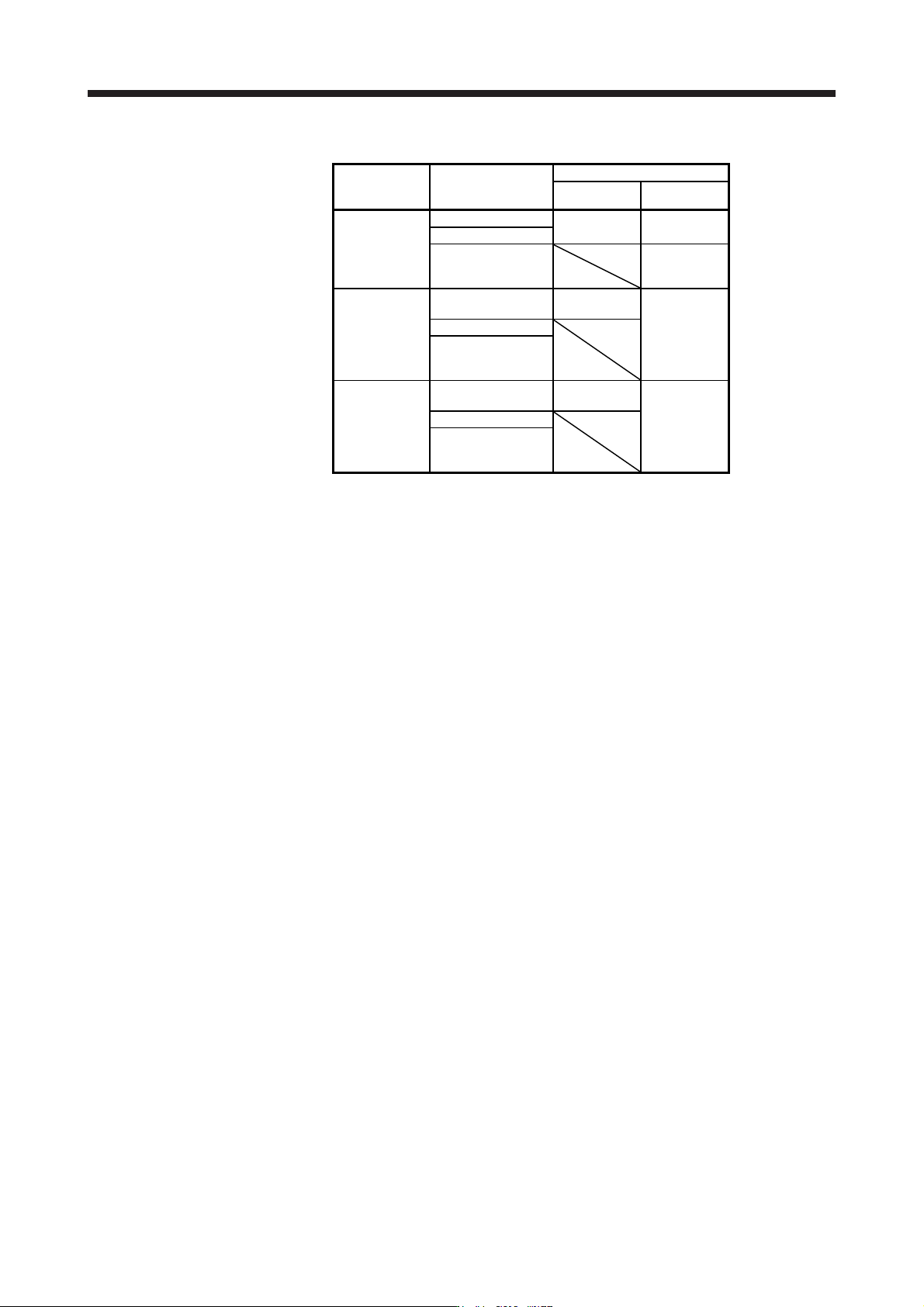
In MELSERVO-J4 series, servo amplifiers with CN2L connector is also available as MR-J4-_B_-RJ. By using
CN2L connector, an A/B/Z-phase differential output method external encoder can be connected to the servo
amplifier. In a fully closed loop system, a four-wire type external encoder is connectable as well. The
following table indicates the communication method of the external encoder compatible with MR-J4-_B_ and
MR-J4-_B_-RJ servo amplifiers.
1. FUNCTIONS AND CONFIGURATION
1 - 2
Table 1.1 Connectors to connect external encoders
Operation
mode
External encoder
communication
method
Connector
MR-J4-_B_ MR-J4-_B_-RJ
Linear servo
system
Two-wire type
CN2 (Note 1) CN2 (Note 1)
Four-wire type
A/B/Z-phase
differential output
method
CN2L (Note 6)
Fully closed
loop system
Two-wire type
CN2
(Note 2, 3, 4)
CN2L
Four-wire type
A/B/Z-phase
differential output
method
Scale
measurement
function
Two-wire type
CN2
(Note 2, 3, 5)
CN2L (Note 5)
Four-wire type
A/B/Z-phase
differential output
method
Note 1. The MR-J4THCBL03M branch cable is necessar
y
.
2. The MR-J4FCCBL03M branch cable is necessar
y
.
3. When the communication method of the servo motor encoder is four-wire type,
MR-J4-
_
B
_
cannot be used. Use an MR-J4-
_
B
_
-RJ.
4. This is used with servo amplifiers with software version A3 or later.
5. This is used with servo amplifiers with software version A8 or later.
6. Connect a thermistor to CN2.
1. FUNCTIONS AND CONFIGURATION
1 - 3
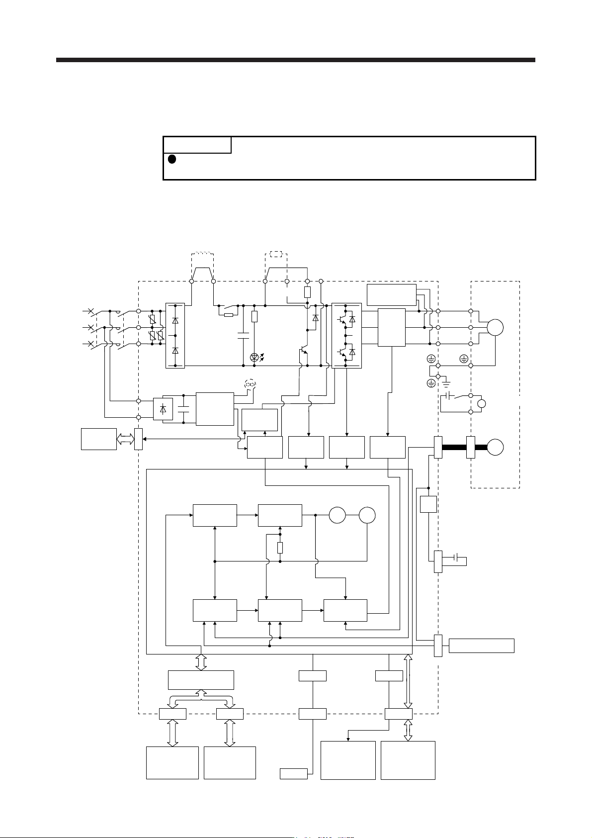
1.2 Function block diagram
The function block diagram of this servo is shown below.
POINT
The diagram shows for MR-J4-_B_-RJ as an example. MR-J4-_B_ servo
amplifier does not have CN2L connector.
(1) 200 V class
(a) MR-J4-500B(-RJ) or less
Model position
Current
control
Actual
position
control
Actual
speed
control
Virtual
motor
Virtual
encoder
L11
L21
Cooling fan
(Note 3)
Encoder
(Note 4)
N-CD
L3
L2
L1
Dynamic
brake
circuit
Power factor improving
DC reactor
Current
detection
Overcurrent
protection
Voltage
detection
(Note 2)
Power
supply
MCMCCB
Base
amplifier
STO
circuit
CN5
USB
USB
Personal
computer
Servo system
controller or
servo amplifier
Servo
amplifier
or cap
CN1A CN1B
D/A
Analog monitor
(2 channels)
Position
command
input
CN3
Servo amplifier
U
V
W
U
V
W
P3 P4
Diode
stack
Relay
P+
+
+
B
RA
24 V DC
B1
B2
Battery
(for absolute position
detection system)
CN4
STO
switch
Model speed Model torque
M
CN2
CN8
Control
circuit
power
supply
Model
position
control
Model
speed
control
I/F Control
Servo motor
CHARGE
lamp
Regene-
rative
TR
Current
encoder
Digital I/O
control
Regenerative
option
U U
U
Step-
down
circuit
Electromagnetic
brake
(Note 1)
(Note 5)
(Note 6)
CN2L
External encoder