sh030106u.pdf - 第198页
5. PARAMETE RS 5 - 53 5.2.7 Linear servo motor/ DD mot or setting param eters ([Pr. PL_ _ ]) No. Sym bol Name and function Initial value [unit] Setting range PL01 **LIT1 Linear serv o motor/DD motor function sel ection 1…
5. PARAMETERS
5 - 52
No. Symbol Name and function
Initial
value
[unit]
Setting
range
PF23 OSCL1 Vibration tough drive - Oscillation detection level
This is used to set a filter readjustment sensitivity of [Pr. PB13 Machine resonance
suppression filter 1] and [Pr. PB15 Machine resonance suppression filter 2] while the vibration
tough drive is enabled.
However, setting "0" will be 50%.
Example: When you set "50" to the parameter, the filter will be readjusted at the time of 50%
or more oscillation level.
50
[%]
0 to 100
PF24 *OSCL2 Vibration tough drive function selection
Refer to the
"Name and
function" column.
Setting
digit
Explanation
Initial
value
_ _ _ x Oscillation detection alarm selection
0: [AL. 54 Oscillation detection] will occur at oscillation detection.
1: [AL. F3.1 Oscillation detection warning] will occur at oscillation
detection.
2: Oscillation detection function disabled
Select alarm or warning when a oscillation continues at a filter
readjustment sensitivity level of [Pr. PF23].
The digit is continuously enabled regardless of the vibration tough
drive in [Pr. PA20].
0h
_ _ x _ For manufacturer setting 0h
_ x _ _ 0h
x _ _ _ 0h
PF25 CVAT SEMI-F47 function - Instantaneous power failure detection time
Set the time of the [AL. 10.1 Voltage drop in the control circuit power] occurrence.
This parameter setting range differs depending on the software version of the servo amplifier
as follows.
Software version C0 or later: Setting range 30 ms to 200 ms
Software version C1 or earlier: Setting range 30 ms to 500 ms
To comply with SEMI-F47 standard, it is unnecessary to change the initial value (200 ms).
When the instantaneous power failure time exceeds 200 ms, and if the instantaneous power
failure voltage is less than 70 % of the rated input voltage, the power may be turned off
normally even if a value larger than 200 ms is set in the parameter.
To disable the parameter, select "Disabled (_ 0 _ _)" of "SEMI-F47 function selection" in [Pr.
PA20].
200
[ms]
30 to
500
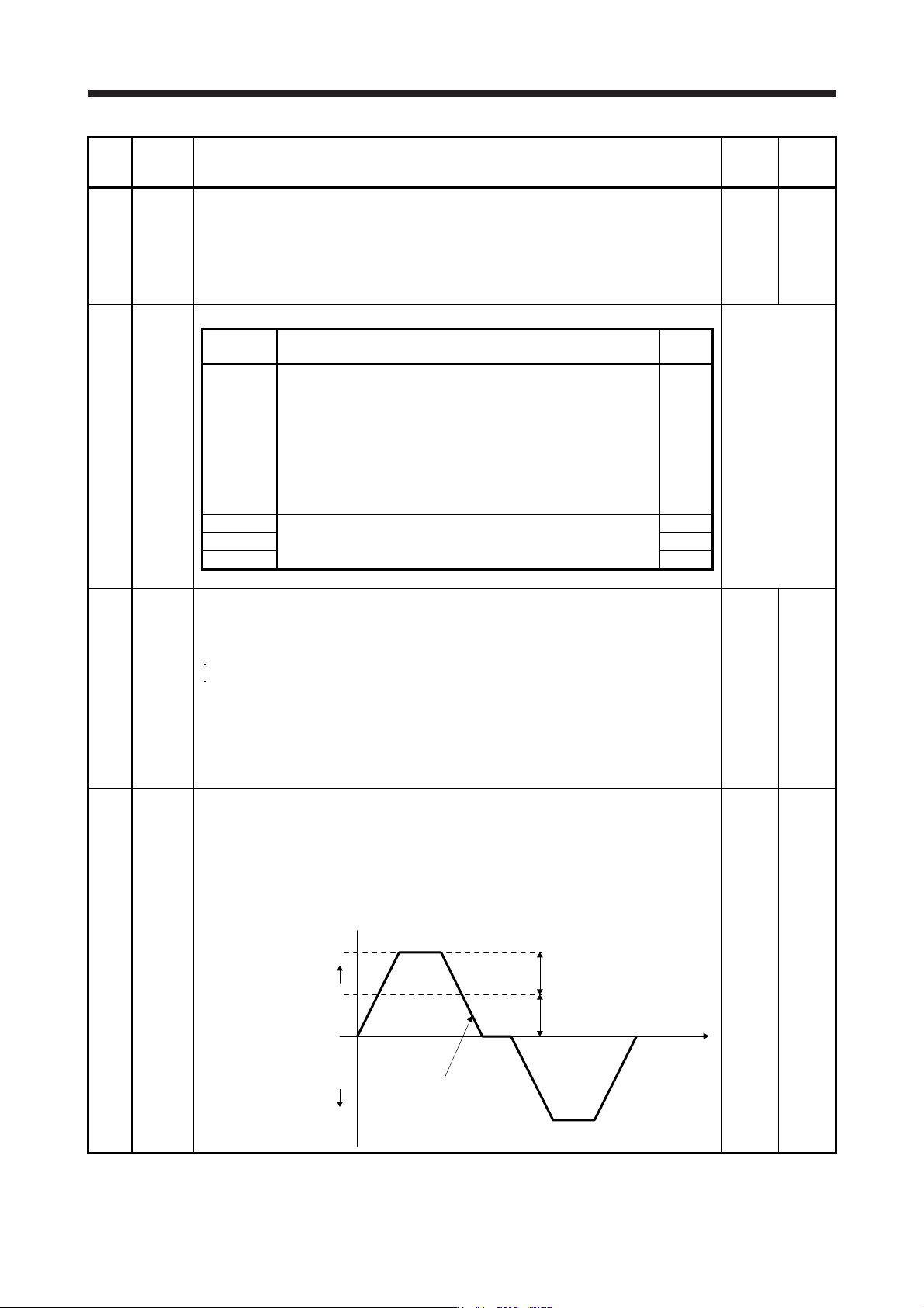
PF31 FRIC Machine diagnosis function - Friction judgment speed
Set a (linear) servo motor speed to divide a friction estimation area into high and low for the
friction estimation process of the machine diagnosis.
However, setting "0" will be the value half of the rated speed.
When your operation pattern is under rated speed, we recommend that you set half value to
the maximum speed with this.
Set a larger value than the one set in [Pr. PC07 Zero speed] in this parameter. If the speed is
the zero speed or less, the friction estimation process is not performed.
Maximum speed in operation
[Pr. PF31] setting
Operation pattern
0 r/min
Servo motor
speed
Forward rotation
direction
Reverse rotation
direction
(0 mm/s)
0
[r/min]/
[mm/s]
0 to
permiss
-ible
speed

5. PARAMETERS
5 - 53
5.2.7 Linear servo motor/DD motor setting parameters ([Pr. PL_ _ ])
No. Symbol Name and function
Initial
value
[unit]
Setting
range
PL01 **LIT1 Linear servo motor/DD motor function selection 1
Select a magnetic pole detection timing of the linear servo motor/DD motor and stop interval
of the home position returning.
Refer to the
"Name and
function" column.
Setting
digit
Explanation
Initial
value
_ _ _ x Linear servo motor/DD motor magnetic pole detection selection
The setting value "0" will be enabled only with absolute position
linear encoders.
0: Magnetic pole detection disabled
1: Magnetic pole detection at first servo-on
5: Magnetic pole detection at every servo-on
1h
_ _ x _ For manufacturer setting 0h
_ x _ _ Stop interval selection at the home position return
Set a stop interval of the home position returning.
The digit is enabled only for linear servo motors.
0: 2
13
(= 8192) pulses
1: 2
17
(= 131072) pulses
2: 2
18
(= 262144) pulses
3: 2
20
(= 1048576) pulses
4: 2
22
(= 4194304) pulses
5: 2
24
(= 16777216) pulses
6: 2
26
(= 67108864) pulses
When "Absolute position detection system selection" is "Enabled (_
_ _ 1)" in [Pr. PA03], setting "0" may prevent the absolute position
from being restored properly.
3h
x _ _ _ For manufacturer setting 0h
PL02 **LIM Linear encoder resolution - Numerator
Set a linear encoder resolution with the settings of [Pr. PL02] and [Pr. PL03].
Set the numerator in [Pr. PL02].
This is enabled only for linear servo motors.
1000
[μm]
1 to
65535
PL03 **LID Linear encoder resolution - Denominator
Set a linear encoder resolution with the settings of [Pr. PL02] and [Pr. PL03].
Set the denominator in [Pr. PL03].
This is enabled only for linear servo motors.
1000
[μm]
1 to
65535
5. PARAMETERS
5 - 54
No. Symbol Name and function
Initial
value
[unit]
Setting
range
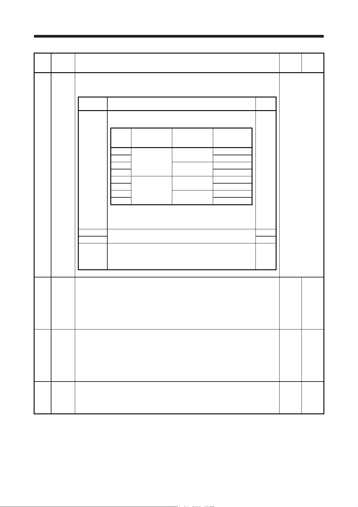
PL04 *LIT2 Linear servo motor/DD motor function selection 2
This is used to select a detection function and detection controller reset condition of [AL. 42
Servo control error].
Refer to the
"Name and
function" column.
Setting
digit
Explanation
Initial
value
_ _ _ x
[AL. 42 Servo control error] detection function selection
Refer to the following table.
3h
Setting
value
Torque/thrust
deviation error
(Note)
Speed deviation
error (Note)
Position
deviation error
(Note)
0
Disabled
Disabled
1
Disabled
Enabled
2
Enabled
Disabled
3 Enabled
4
Disabled
Disabled
5
Enabled
Enabled
6
Enabled
Disabled
7 Enabled
Note. Refer to chapter 14 and 15 for details of each deviation
error.
_ _ x _ For manufacturer setting 0h
_ x _ _ 0h
x _ _ _
[AL. 42 Servo control error] detection function controller reset
condition selection
0: Reset disabled (reset by powering off/on enabled)
1: Reset enabled
0h
PL05 LB1 Position deviation error detection level
This is used to set the position deviation error detection level of the servo control error
detection.
When the deviation between a model feedback position and actual feedback position is larger
than the setting value, [AL. 42 Servo control error] will occur.
However, when "0" is set, the level vary depending on the operation mode in [Pr. PA01].
Linear servo motor: 50 mm
Direct drive motor: 0.09 rev
0
[mm]/
[0.01 rev]
0 to
1000
PL06 LB2 Speed deviation error detection level
This is used to set the speed deviation error detection level of the servo control error
detection.
When the deviation between a model feedback speed and actual feedback speed is larger
than the setting value, [AL. 42 Servo control error] will occur.
However, when "0" is set, the level vary depending on the operation mode in [Pr. PA01].
Linear servo motor: 1000 mm/s
Direct drive motor: 100 r/min
0
[mm/s]/
[r/min]
0 to
5000
PL07 LB3 Torque/thrust deviation error detection level
This is used to set the torque/thrust deviation error detection level of the servo control error
detection.
When the deviation between a current command and current feedback is larger than the
setting value, [AL. 42.3 Servo control error by torque/thrust deviation] will occur.
100
[%]
0 to
1000