sh030106u.pdf - 第20页
1. FUNCTI ONS AND CONF IGURATION 1 - 3 1.2 Func tion bloc k diagr am The functio n block diagram of th is serv o is show n belo w. POINT The diagra m shows f or MR -J4-_B_- RJ as an example . MR- J4-_B_ s er vo amplif ie…

1. FUNCTIONS AND CONFIGURATION
1 - 2
Table 1.1 Connectors to connect external encoders
Operation
mode
External encoder
communication
method
Connector
MR-J4-_B_ MR-J4-_B_-RJ
Linear servo
system
Two-wire type
CN2 (Note 1) CN2 (Note 1)
Four-wire type
A/B/Z-phase
differential output
method
CN2L (Note 6)
Fully closed
loop system
Two-wire type
CN2
(Note 2, 3, 4)
CN2L
Four-wire type
A/B/Z-phase
differential output
method
Scale
measurement
function
Two-wire type
CN2
(Note 2, 3, 5)
CN2L (Note 5)
Four-wire type
A/B/Z-phase
differential output
method
Note 1. The MR-J4THCBL03M branch cable is necessar
y
.
2. The MR-J4FCCBL03M branch cable is necessar
y
.
3. When the communication method of the servo motor encoder is four-wire type,
MR-J4-
_
B
_
cannot be used. Use an MR-J4-
_
B
_
-RJ.
4. This is used with servo amplifiers with software version A3 or later.
5. This is used with servo amplifiers with software version A8 or later.
6. Connect a thermistor to CN2.
1. FUNCTIONS AND CONFIGURATION
1 - 3
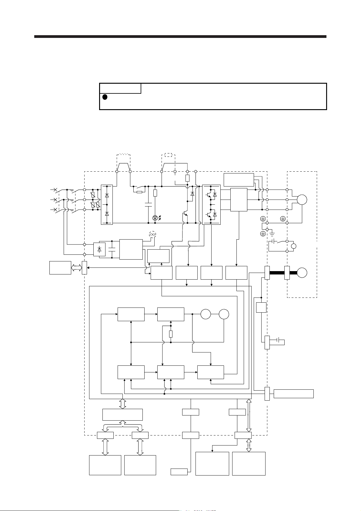
1.2 Function block diagram
The function block diagram of this servo is shown below.
POINT
The diagram shows for MR-J4-_B_-RJ as an example. MR-J4-_B_ servo
amplifier does not have CN2L connector.
(1) 200 V class
(a) MR-J4-500B(-RJ) or less
Model position
Current
control
Actual
position
control
Actual
speed
control
Virtual
motor
Virtual
encoder
L11
L21
Cooling fan
(Note 3)
Encoder
(Note 4)
N-CD
L3
L2
L1
Dynamic
brake
circuit
Power factor improving
DC reactor
Current
detection
Overcurrent
protection
Voltage
detection
(Note 2)
Power
supply
MCMCCB
Base
amplifier
STO
circuit
CN5
USB
USB
Personal
computer
Servo system
controller or
servo amplifier
Servo
amplifier
or cap
CN1A CN1B
D/A
Analog monitor
(2 channels)
Position
command
input
CN3
Servo amplifier
U
V
W
U
V
W
P3 P4
Diode
stack
Relay
P+
+
+
B
RA
24 V DC
B1
B2
Battery
(for absolute position
detection system)
CN4
STO
switch
Model speed Model torque
M
CN2
CN8
Control
circuit
power
supply
Model
position
control
Model
speed
control
I/F Control
Servo motor
CHARGE
lamp
Regene-
rative
TR
Current
encoder
Digital I/O
control
Regenerative
option
U U
U
Step-
down
circuit
Electromagnetic
brake
(Note 1)
(Note 5)
(Note 6)
CN2L
External encoder

1. FUNCTIONS AND CONFIGURATION
1 - 4
Note 1. The built-in re
g
enerative resistor is not provided for MR-J4-10B
(
-RJ
)
.
2. For 1-phase 200 V AC to 240 V AC, connect the power supply to L1 and L3. Leave L2 open. Refer to section 1.3 for the power
suppl
y
specifications.
3. Servo amplifiers MR-J4-70B
(
-RJ
)
or more have a coolin
g
fan.
4. MR-J4 servo amplifier has P3 and P4 in the upstream of the inrush current suppression circuit. They are different from P1 and
P2 of MR-J3 servo amplifiers.
5. This is for MR-J4-
_
B-RJ servo amplifier. MR-J4-
_
B servo amplifier does not have CN2L connector.
6. The power factor improving AC reactor can also be used. In this case, the power factor improving DC reactor cannot be used.
When not usin
g
the power factor improvin
g
DC reactor, short P3 and P4.