sh030106u.pdf - 第200页
5. PARAMETE RS 5 - 55 No. Sym bol Name and function Initial value [unit] Setting range PL08 *LI T3 Linear serv o motor/DD motor f unction selection 3 Refer to t he "Name and function" c olumn. Setting digit Exp…
5. PARAMETERS
5 - 54
No. Symbol Name and function
Initial
value
[unit]
Setting
range
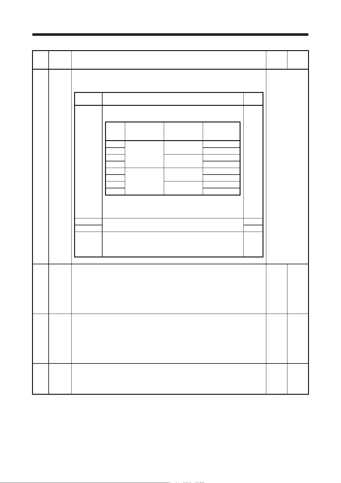
PL04 *LIT2 Linear servo motor/DD motor function selection 2
This is used to select a detection function and detection controller reset condition of [AL. 42
Servo control error].
Refer to the
"Name and
function" column.
Setting
digit
Explanation
Initial
value
_ _ _ x
[AL. 42 Servo control error] detection function selection
Refer to the following table.
3h
Setting
value
Torque/thrust
deviation error
(Note)
Speed deviation
error (Note)
Position
deviation error
(Note)
0
Disabled
Disabled
1
Disabled
Enabled
2
Enabled
Disabled
3 Enabled
4
Disabled
Disabled
5
Enabled
Enabled
6
Enabled
Disabled
7 Enabled
Note. Refer to chapter 14 and 15 for details of each deviation
error.
_ _ x _ For manufacturer setting 0h
_ x _ _ 0h
x _ _ _
[AL. 42 Servo control error] detection function controller reset
condition selection
0: Reset disabled (reset by powering off/on enabled)
1: Reset enabled
0h
PL05 LB1 Position deviation error detection level
This is used to set the position deviation error detection level of the servo control error
detection.
When the deviation between a model feedback position and actual feedback position is larger
than the setting value, [AL. 42 Servo control error] will occur.
However, when "0" is set, the level vary depending on the operation mode in [Pr. PA01].
Linear servo motor: 50 mm
Direct drive motor: 0.09 rev
0
[mm]/
[0.01 rev]
0 to
1000
PL06 LB2 Speed deviation error detection level
This is used to set the speed deviation error detection level of the servo control error
detection.
When the deviation between a model feedback speed and actual feedback speed is larger
than the setting value, [AL. 42 Servo control error] will occur.
However, when "0" is set, the level vary depending on the operation mode in [Pr. PA01].
Linear servo motor: 1000 mm/s
Direct drive motor: 100 r/min
0
[mm/s]/
[r/min]
0 to
5000
PL07 LB3 Torque/thrust deviation error detection level
This is used to set the torque/thrust deviation error detection level of the servo control error
detection.
When the deviation between a current command and current feedback is larger than the
setting value, [AL. 42.3 Servo control error by torque/thrust deviation] will occur.
100
[%]
0 to
1000

5. PARAMETERS
5 - 55
No. Symbol Name and function
Initial
value
[unit]
Setting
range
PL08 *LIT3 Linear servo motor/DD motor function selection 3
Refer to the
"Name and
function" column.
Setting
digit
Explanation
Initial
value
_ _ _ x
Magnetic pole detection method selection
0: Position detection method
4: Minute position detection method
0h
_ _ x _ For manufacturer setting 1h
_ x _ _
Magnetic pole detection - Stroke limit enabled/disabled selection
0: Enabled
1: Disabled
0h
x _ _ _
Minute position detection method - High-resolution encoder
selection
0: Disabled
1: Enabled
This digit will be enabled when "minute position detection method"
is selected in [Pr. PL08 (_ _ _ x)].
If a linear encoder whose resolution is smaller than 0.05 μm is used
and also [AL. 27 Initial magnetic pole detection error] occurs
because the travel distance at magnetic pole detection is too large
or vibration occurs, set "1" (enabled).
This digit is available on servo amplifiers with software version A8
or later.
0h
PL09 LPWM Magnetic pole detection voltage level
This is used to set a direct current exciting voltage level during the magnetic pole detection.
If [AL. 32 Overcurrent], [AL. 50 Overload 1], or [AL. 51 Overload 2] occurs during the magnetic
pole detection, decrease the setting value.
If [AL. 27 Initial magnetic pole detection error] occurs during the magnetic pole detection,
increase the setting value.
30
[%]
0 to 100
5. PARAMETERS
5 - 56
No. Symbol Name and function
Initial
value
[unit]
Setting
range
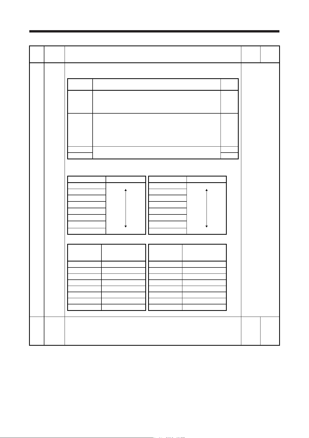
PL17 LTSTS Magnetic pole detection - Minute position detection method - Function selection
To enable the parameter, select "Minute position detection method (_ _ _ 4)" in [Pr. PL08].
Refer to the
"Name and
function" column.
Setting
digit
Explanation
Initial
value
_ _ _ x Response selection
Set a response of the minute position detection method.
When reducing a travel distance at the magnetic pole detection,
increase the setting value. Refer to table 5.9 for settings.
0h
_ _ x _ Load to motor mass ratio/load to motor inertia ratio selection
Select a load to mass of the linear servo motor primary-side ratio or
load to mass of the direct drive motor inertia ratio used at the
minute position detection method. Set a closest value to the actual
load.
Refer to table 5.10 for settings.
0h
_ x _ _ For manufacturer setting 0h
x _ _ _ 0h
Table 5.9 Response of minute position detection method at magnetic
pole detection
Setting value Response Setting value Response
_ _ _ 0 Low response _ _ _ 8 Middle response
_ _ _ 1
_ _ _ 9
_ _ _ 2 _ _ _ A
_ _ _ 3 _ _ _ B
_ _ _ 4 _ _ _ C
_ _ _ 5 _ _ _ D
_ _ _ 6 _ _ _ E
_ _ _ 7 Middle response _ _ _ F High response
Table 5.10 Load to motor mass ratio/load to motor inertia ratio
Setting value
Load to motor mass
ratio/load to motor
inertia ratio
Setting value
Load to motor mass
ratio/load to motor
inertia ratio
_ _ 0 _ 10 times or less _ _ 8 _ 80 times
_ _ 1 _ 10 times _ _ 9 _ 90 times
_ _ 2 _ 20 times _ _ A _ 100 times
_ _ 3 _ 30 times _ _ B _ 110 times
_ _ 4 _ 40 times _ _ C _ 120 times
_ _ 5 _ 50 times _ _ D _ 130 times
_ _ 6 _ 60 times _ _ E _ 140 times
_ _ 7 _ 70 times _ _ F _ 150 times or more
PL18 IDLV Magnetic pole detection - Minute position detection method - Identification signal amplitude
Set an identification signal amplitude used in the minute position detection method.
This parameter is enabled only when the magnetic pole detection is the minute position
detection method.
However, setting "0" will be 100% amplitude.
0
[%]
0 to 100