sh030106u.pdf - 第205页
6. NORM AL GAIN ADJ USTMENT 6 - 4 The foll owing par ameters are s et automatic ally with one-touc h tuni ng. Als o, "Gain adj ustment m ode selecti on" in [Pr . PA08] will be "2 g ain adjus tment mode 2 (…
6. NORMAL GAIN ADJUSTMENT
6 - 3
6.2 One-touch tuning
POINT
After the one-touch tuning is completed, "Gain adjustment mode selection" in
[Pr. PA08] will be set to "2 gain adjustment mode 2 (_ _ _ 4)". To estimate [Pr.
PB06 Load to motor inertia ratio/load to motor mass ratio] again, set "Gain
adjustment mode selection" in [Pr. PA08] to "Auto tuning mode 1 (_ _ _ 1)".
When executing the one-touch tuning, check the [Pr. PA21 One-touch tuning
function selection] is "_ _ _ 1" (initial value).
At start of the one-touch tuning, only when "Auto tuning mode 1 (_ _ _ 1)" or "2
gain adjustment mode 1 (interpolation mode) (_ _ _ 0)" of "Gain adjustment
mode selection" is selected in [Pr. PA08], [Pr. PB06 Load to motor inertia ratio/
load to motor mass ratio] will be estimated.
Execute the one-touch tuning while the servo system controller and the servo
amplifier are connected.
When executing the one-touch tuning in the test operation mode (SW2-1 is on),
write the tuning result to servo parameters of the servo system controller, and
then connect the servo system controller and the servo amplifier.
The amplifier command method can be used with the servo amplifier with
software version C1 or later and MR Configurator2 with software version 1.45X
or later.
When the one-touch tuning is executed, MR Configurator2 is required.
The one-touch tuning includes two methods: the user command method and the amplifier command method.
(1) User command method
The user command method performs one-touch tuning by inputting commands from outside the servo
amplifier.
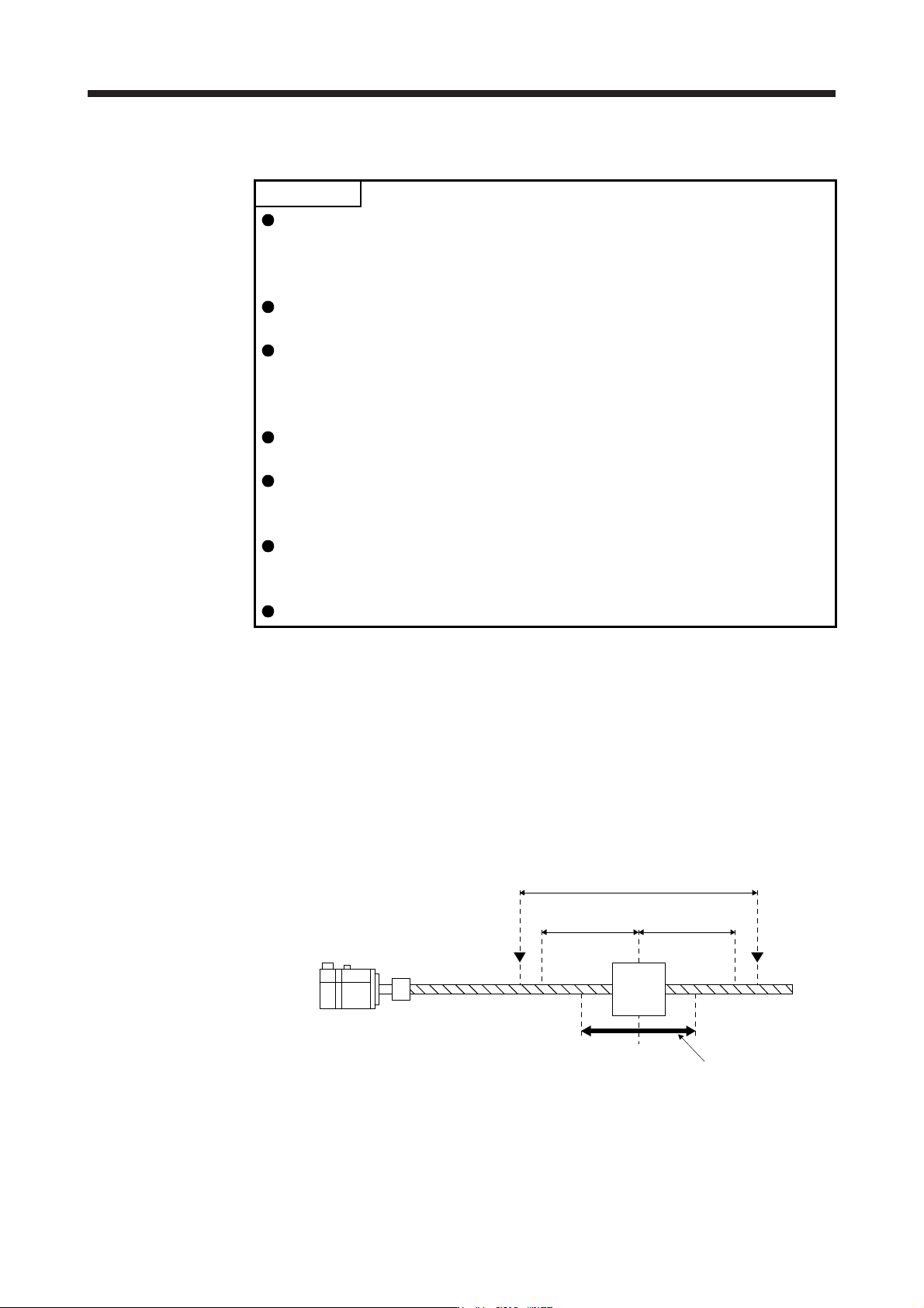
(2) Amplifier command method
In the amplifier command method, when you simply input a travel distance (permissible travel distance)
that collision against the equipment does not occur during servo motor driving, a command for the
optimum tuning will be generated inside the servo amplifier to perform one-touch tuning.
Servo motor
Moving
part
Movable range
Tuning start position
Movable range at tuning
Permissible
travel distance
Limit switch
Permissible
travel distance
Limit switch
6. NORMAL GAIN ADJUSTMENT
6 - 4
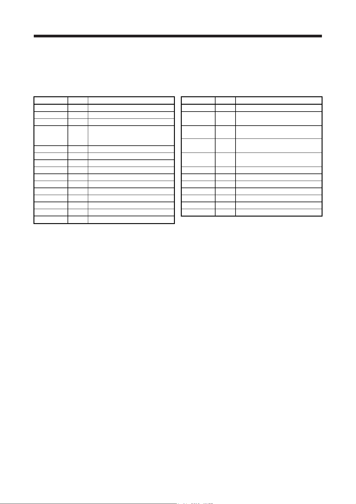
The following parameters are set automatically with one-touch tuning. Also, "Gain adjustment mode
selection" in [Pr. PA08] will be "2 gain adjustment mode 2 (_ _ _ 4)" automatically. Other parameters will
be set to an optimum value depending on the setting of [Pr. PA09 Auto tuning response].
Table 6.1 List of parameters automatically set with one-touch tuning
Parameter Symbol Name Parameter Symbol Name
PA08 ATU Auto tuning mode PB18 LPF Low-pass filter setting
PA09 RSP Auto tuning response
PB19 VRF11
Vibration suppression control 1 -
Vibration frequency
PB01 FILT Adaptive tuning mode (adaptive filter II)
PB02 VRFT
Vibration suppression control tuning
mode (advanced vibration suppression
control II)
PB20 VRF12
Vibration suppression control 1 -
Resonance frequency
PB21 VRF13
Vibration suppression control 1 -
Vibration frequency damping
PB06 GD2 Load to motor inertia ratio
PB07 PG1 Model loop gain
PB22 VRF14
Vibration suppression control 1 -
Resonance frequency damping
PB08 PG2 Position loop gain
PB09 VG2 Speed loop gain PB23 VFBF Low-pass filter selection
PB10 VIC Speed integral compensation PB46 NH3 Machine resonance suppression filter 3
PB12 OVA Overshoot amount compensation PB47 NHQ3 Notch shape selection 3
PB13 NH1 Machine resonance suppression filter 1 PB48 NH4 Machine resonance suppression filter 4
PB14 NHQ1 Notch shape selection 1 PB49 NHQ4 Notch shape selection 4
PB15 NH2 Machine resonance suppression filter 2 PB51 NHQ5 Notch shape selection 5
PB16 NHQ2 Notch shape selection 2 PE41 EOP3 Function selection E-3
PB17 NHF Shaft resonance suppression filter
6. NORMAL GAIN ADJUSTMENT
6 - 5
6.2.1 One-touch tuning flowchart
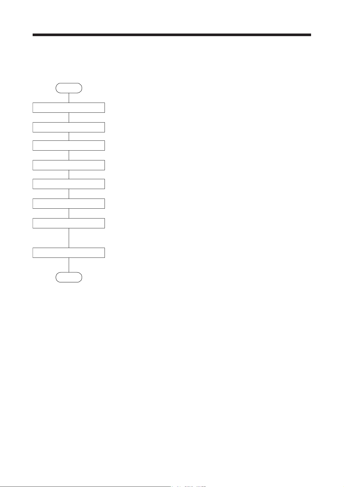
(1) User command method
Make one-touch tuning as follows.
Start
Startup of the system
Operation
One-touch tuning start,
mode selection
Response mode selection
One-touch tuning execution
One-touch tuning completion
Tuning result check
One-touch tuning in progress
End
Start a system referring to chapter 4.
Rotate the servo motor by a servo system controller. (In the user command method, the one-
touch tuning cannot be executed if the servo motor is not operating.)
Start one-touch tuning of MR Configurator2, and select "User command method".
Select a response mode (High mode, Basic mode, and Low mode) in the one-touch tuning
window of MR Configurator2.
Click "Start" during servo motor driving to execute one-touch tuning.
Gains and filters will be adjusted automatically. During processing of tuning, the tuning progress
will be displayed in % in MR Configurator2.
When one-touch tuning is completed normally, the parameters described in table 6.1 will be set
automatically.
When the tuning is not completed normally, the tuning error will be displayed. (Refer to section
6.2.2 (5).)
Check the tuning result.
When the tuning result is not satisfactory, you can return the parameter to the value before the
one-touch tuning or the initial value. (Refer to section 6.2.2 (8).)