sh030106u.pdf - 第218页
6. NORM AL GAIN ADJ USTMENT 6 - 17 6.2.3 Caut ion for one-touc h tun ing (1) Caution co mmon f or user command method and am plifier comman d meth od (a) The tu ning is not av ailable in the torqu e contr ol mod e. (b) T…
6. NORMAL GAIN ADJUSTMENT
6 - 16
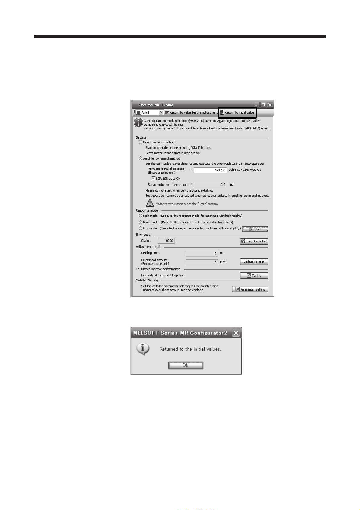
(8) Initializing one-touch tuning
Clicking "Return to initial value" in the one-touch tuning window of MR Configurator2 enables to return
the parameter to the initial value. Refer to table 6.1 for the parameters which you can initialize.
Clicking "Return to value before adjustment" in the one-touch tuning window of MR Configurator2
enables to return the parameter to the value before clicking "start".
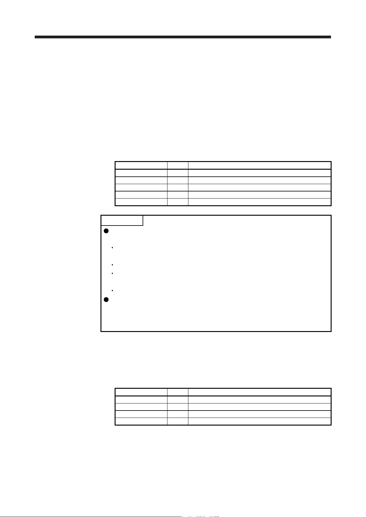
When the initialization of one-touch tuning is completed, the following window will be displayed.
(returning to initial value)

6. NORMAL GAIN ADJUSTMENT
6 - 17
6.2.3 Caution for one-touch tuning
(1) Caution common for user command method and amplifier command method
(a) The tuning is not available in the torque control mode.
(b) The one-touch tuning cannot be executed while an alarm or warning which does not continue the
motor driving is occurring.
(c) The one-touch tuning cannot be executed during the following test operation mode.
1) Output signal (DO) forced output
2) Motor-less operation
(d) If one-touch tuning is performed when the gain switching function is enabled, vibration and/or
unusual noise may occur during the tuning.
(2) Caution for amplifier command method
(a) Starting one-touch tuning while the servo motor is rotating displays "C006" at status in error code,
and the one-touch tuning cannot be executed.
(b) One-touch tuning is not available during the test operation mode. The following test operation modes
cannot be executed during one-touch tuning.
1) Positioning operation
2) JOG operation
3) Program operation
4) Machine analyzer operation
(c) After one-touch tuning is executed, control will not be performed by commands from the servo
system controller. To return to the state in which control is performed from the servo system
controller, reset the controller or cycle the power of the servo amplifier.
(d) During one-touch tuning, the permissible travel distance may be exceeded due to overshoot, set a
value sufficient to prevent machine collision.
(e) When Auto tuning mode 2, Manual mode, or 2 gain adjustment mode 2 is selected in [Pr. PA08 Auto
tuning mode], the load to motor inertia ratio will not be estimated. An optimum
acceleration/deceleration command will be generated by [Pr. PB06 Load to motor inertia ratio/load to
motor mass ratio] at the start of one-touch tuning. When the load to motor inertia ratio is incorrect,
the optimum acceleration/deceleration command may not be generated, causing the tuning to fail.
(f) When one-touch tuning is started by using USB communication, if the USB communication is
interrupted during the tuning, the servo motor will stop, and the tuning will also stop. The parameter
will return to the one at the start of the one-touch tuning.
(g) When one-touch tuning is started via the controller, if communication between the controller and the
servo amplifier or personal computer is shut-off during the tuning, the servo motor will stop, and the
tuning will also stop. The parameter will return to the one at the start of the one-touch tuning.
(h) When one-touch tuning is started during the speed control mode, the mode will be switched to the
position control mode automatically. The tuning result may differ from the one obtained by executing
tuning by using the speed command.
6. NORMAL GAIN ADJUSTMENT
6 - 18
6.3 Auto tuning
6.3.1 Auto tuning mode
The servo amplifier has a real-time auto tuning function which estimates the machine characteristic (load to
motor inertia ratio) in real time and automatically sets the optimum gains according to that value. This
function permits ease of gain adjustment of the servo amplifier.
(1) Auto tuning mode 1
The servo amplifier is factory-set to the auto tuning mode 1.
In this mode, the load to motor inertia ratio of a machine is always estimated to set the optimum gains
automatically.
The following parameters are automatically adjusted in the auto tuning mode 1.
Parameter Symbol Name
PB06 GD2 Load to motor inertia ratio/load to motor mass ratio
PB07 PG1 Model loop gain
PB08 PG2 Position loop gain
PB09 VG2 Speed loop gain
PB10 VIC Speed integral compensation
POINT
The auto tuning mode 1 may not be performed properly if all of the following
conditions are not satisfied.
The acceleration/deceleration time constant to reach 2000 r/min (mm/s) is 5 s
or less.
Speed is 150 r/min (mm/s) or higher.
The load to servo motor (mass of linear servo motor's primary side or direct
drive motor) inertia ratio is 100 times or less.
The acceleration/deceleration torque is 10% or more of the rated torque.
Under operating conditions which will impose sudden disturbance torque during
acceleration/deceleration or on a machine which is extremely loose, auto tuning
may not function properly, either. In such cases, use the auto tuning mode 2 or
manual mode to make gain adjustment.
(2) Auto tuning mode 2
Use the auto tuning mode 2 when proper gain adjustment cannot be made by auto tuning mode 1. Since
the load to motor inertia ratio is not estimated in this mode, set the value of a correct load to motor inertia
ratio in [Pr. PB06].
The following parameters are automatically adjusted in the auto tuning mode 2.
Parameter Symbol Name
PB07 PG1 Model loop gain
PB08 PG2 Position loop gain
PB09 VG2 Speed loop gain
PB10 VIC Speed integral compensation