sh030106u.pdf - 第226页
6. NORM AL GAIN ADJ USTMENT 6 - 25 3) [Pr. P B08 Pos ition lo op gai n] This para meter det ermi nes the r espons e level to a dis turbanc e t o th e positi on con trol loop . Increasing the v alue inc reas es the respo …

6. NORMAL GAIN ADJUSTMENT
6 - 24
(b) Adjustment procedure
Step Operation Description
1 Brief-adjust with auto tuning. Refer to section 6.2.3.
2
Change the setting of auto tuning to the manual mode ([Pr.
PA08]: _ _ _ 3).
3
Set the estimated value to the load to motor inertia ratio/load to
motor mass ratio. (If the estimate value with auto tuning is
correct, setting change is not required.)
4
Set a small value to the model loop gain.
Set a large value to the speed integral compensation.
5
Increase the speed loop gain within the vibration- and unusual
noise-free range, and return slightly if vibration takes place.
Increase the speed loop
gain.
6
Decrease the speed integral compensation within the vibration-
free range, and return slightly if vibration takes place.
Decrease the time
constant of the speed
integral compensation.
7
Increase the position loop gain, and return slightly if vibration
takes place.
Increase the position loop
gain.
8
Increase the model loop gain, and return slightly if overshoot
takes place.
Increase the model loop
gain.
9
If the gains cannot be increased due to mechanical system
resonance or the like and the desired response cannot be
achieved, response may be increased by suppressing resonance
with the adaptive tuning mode or machine resonance
suppression filter and then executing steps 3 to 8.
Suppression of machine
resonance
Refer to section 7.2 and
7.3.
10
While checking the settling characteristic and motor status, fine-
adjust each gain.
Fine adjustment
(c) Parameter adjustment
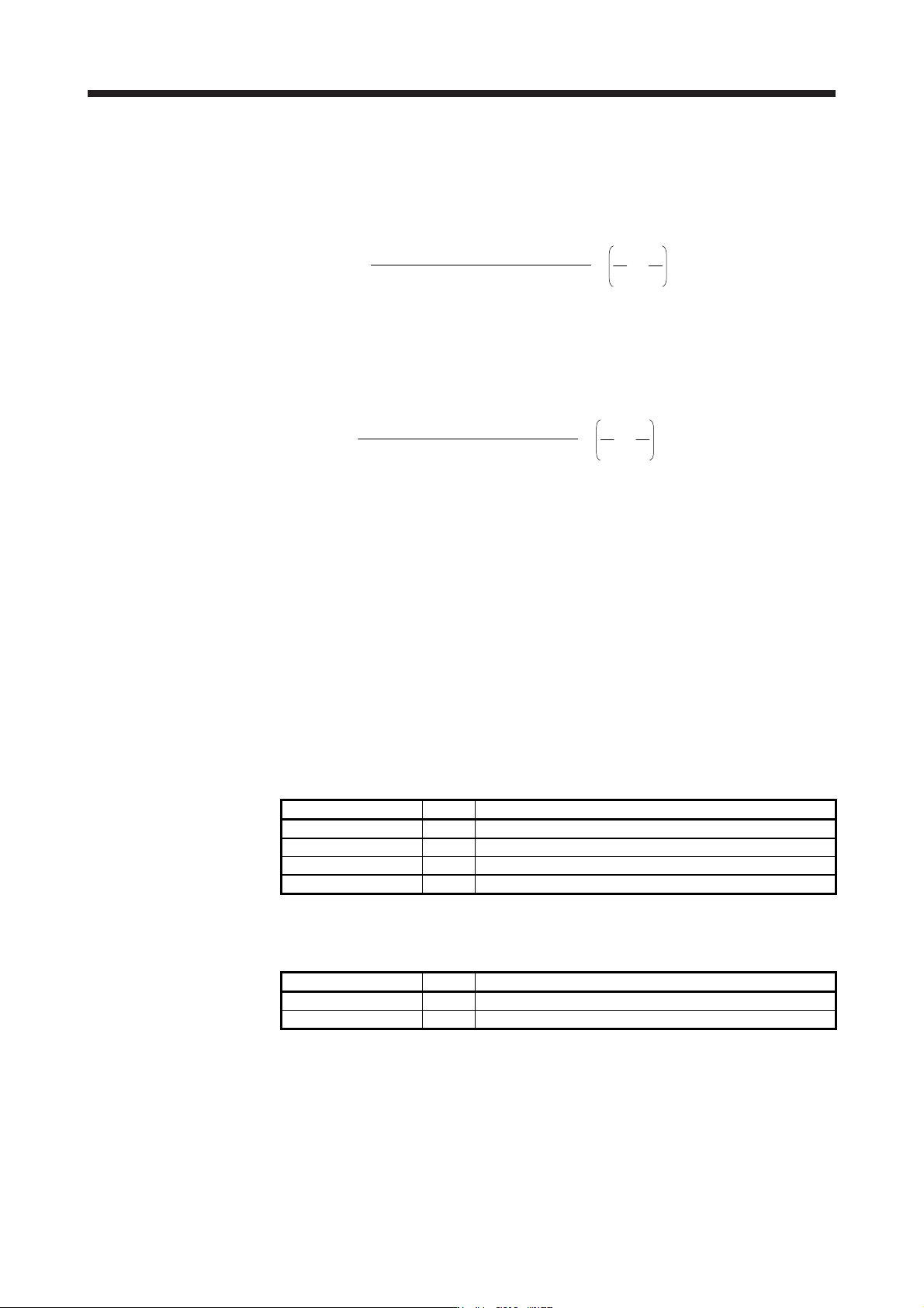
1) [Pr. PB09 Speed loop gain]
This parameter determines the response level of the speed control loop. Increasing this value will
improve responsiveness, but increasing the value excessively will cause the mechanical system
to easily vibrate. The actual response frequency of the speed loop is as indicated in the following
expression.
Speed loop response frequency [Hz] =
(1 + Load to motor inertia ratio) × 2
Speed loop gain
2) [Pr. PB10 Speed integral compensation]
To eliminate stationary deviation against a command, the speed control loop is under proportional
integral control. For the speed integral compensation, set the time constant of this integral control.
Increasing the setting lowers the response level. However, if the load to motor inertia ratio is large
or the mechanical system has any vibratory element, the mechanical system is liable to vibrate
unless the setting is increased to some degree. The guideline is as indicated in the following
expression.
Speed integral compensation setting [ms]
≥
2000 to 3000
Speed loop gain/(1 + Load to motor inertia ratio
)
6. NORMAL GAIN ADJUSTMENT
6 - 25
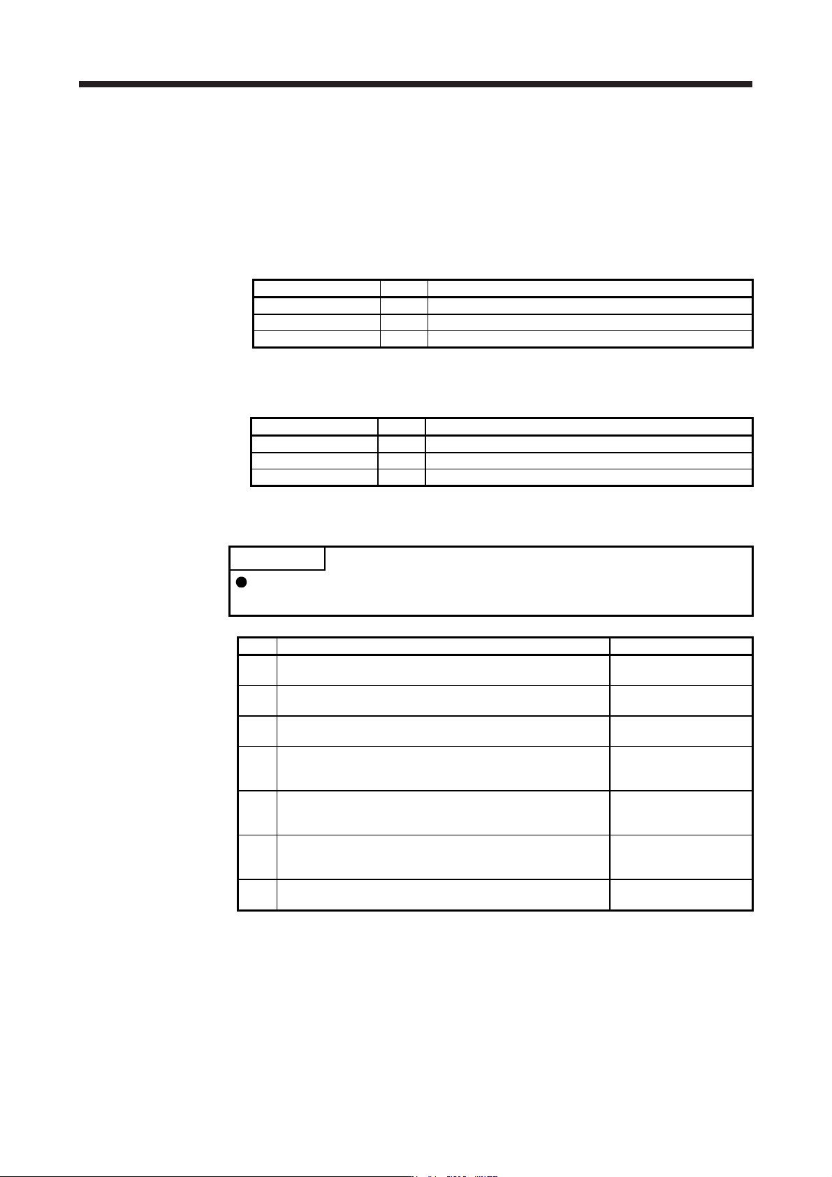
3) [Pr. PB08 Position loop gain]
This parameter determines the response level to a disturbance to the position control loop.
Increasing the value increases the response level to the disturbance, but a too high value will
increase vibration of the mechanical system.
Position loop gain guideline ≤
(1 + Load to motor inertia ratio)
Speed loop gain
×
8
1
4
1
to
4) [Pr. PB07 Model loop gain]
This parameter determines the response level to a position command. Increasing the value
improves trackability to a position command, but a too high value will make overshoot liable to
occur at settling.
Model loop gain guideline ≤
(1 + Load to motor inertia ratio)
Speed loop gain
×
8
1
4
1
to
6.5 2 gain adjustment mode
The 2 gain adjustment mode is used to match the position loop gains of the axes when performing the
interpolation operation of servo motors of two or more axes for an X-Y table or the like. In this mode,
manually set the model loop gain that determines command trackability. Other parameters for gain
adjustment are set automatically.
(1) 2 gain adjustment mode 1 (interpolation mode)
The 2 gain adjustment mode 1 manually set the model loop gain that determines command trackability.
The mode constantly estimates the load to motor inertia ratio, and automatically set other parameters for
gain adjustment to optimum gains using auto tuning response.
The following parameters are used for 2 gain adjustment mode 1.
(a) Automatically adjusted parameter
The following parameters are automatically adjusted by auto tuning.
Parameter Symbol Name
PB06 GD2 Load to motor inertia ratio/load to motor mass ratio
PB08 PG2 Position loop gain
PB09 VG2 Speed loop gain
PB10 VIC Speed integral compensation
(b) Manually adjusted parameter
The following parameters are adjustable manually.
Parameter Symbol Name
PA09 RSP Auto tuning response
PB07 PG1 Model loop gain
6. NORMAL GAIN ADJUSTMENT
6 - 26
(2) 2 gain adjustment mode 2
Use 2 gain adjustment mode 2 when proper gain adjustment cannot be made with 2 gain adjustment
mode 1. Since the load to motor inertia ratio is not estimated in this mode, set the value of a proper load
to motor inertia ratio in [Pr. PB06].
The following parameters are used for 2 gain adjustment mode 2.
(a) Automatically adjusted parameter
The following parameters are automatically adjusted by auto tuning.
Parameter Symbol Name
PB08 PG2 Position loop gain
PB09 VG2 Speed loop gain
PB10 VIC Speed integral compensation
(b) Manually adjusted parameter
The following parameters are adjustable manually.
Parameter Symbol Name
PA09 RSP Auto tuning response
PB06 GD2 Load to motor inertia ratio/load to motor mass ratio
PB07 PG1 Model loop gain
(3) Adjustment procedure of 2 gain adjustment mode
POINT
Set the same value in [Pr. PB07 Model loop gain] for the axis used in 2 gain
adjustment mode.
Step Operation Description
1 Set to the auto tuning mode.
Select the auto tuning
mode 1.
2
During operation, increase the response level setting value in [Pr.
PA09], and return the setting if vibration occurs.
Adjustment in auto tuning
mode 1.
3
Check value of the model loop gain and the load to motor inertia
ratio in advance.
Check the upper setting
limits.
4
Set the 2 gain adjustment mode 1 ([Pr. PA08]: _ _ _ 0).
Select the 2 gain
adjustment mode 1
(interpolation mode).
5
When the load to motor inertia ratio is different from the design
value, select the 2 gain adjustment mode 2 ([Pr. PA08]: _ _ _ 4)
and then set the load to motor inertia ratio manually in [Pr. PB06].
Check the load to motor
inertia ratio.
6
Set the model loop gain of all the axes to be interpolated to the
same value. At that time, adjust to the setting value of the axis,
which has the smallest model loop gain.
Set model loop gain.
7
Considering the interpolation characteristic and motor status,
fine-adjust the model loop gain and response level setting.
Fine adjustment