sh030106u.pdf - 第242页
7. SPEC IAL ADJUSTMEN T FUNCT IONS 7 - 13 (b) When v ibratio n can be conf irmed using m onitor signa l or ex t erna l sensor t Motor-side vibration (droop pulses) Position command frequency t External acceleration picku…
7. SPECIAL ADJUSTMENT FUNCTIONS
7 - 12
Step 1 Select "Manual setting (_ _ _ 2)" of "Vibration suppression control 1 tuning mode selection" or
"Manual setting (_ _ 2 _)" of "Vibration suppression control 2 tuning mode selection" in [Pr.
PB02].
Step 2 Set "Vibration suppression control - Vibration frequency" and "Vibration suppression control -
Resonance frequency" as follows.
However, the value of [Pr. PB07 Model loop gain], vibration frequency, and resonance frequency have
the following usable range and recommended range.
Vibration suppression
control
Usable range Recommended setting range
Vibration suppression
control 1
[Pr. PB19] > 1/2π × (0.9 × [Pr. PB07])
[Pr. PB20] > 1/2π × (0.9 × [Pr. PB07])
[Pr. PB19] > 1/2π × (1.5 × [Pr. PB07])
[Pr. PB20] > 1/2π × (1.5 × [Pr. PB07])
Vibration suppression
control 2
When [Pr. PB19] < [Pr. PB52],
[Pr. PB52] > (5.0 + 0.1 × [Pr. PB07])
[Pr. PB53] > (5.0 + 0.1 × [Pr. PB07])
1.1 < [Pr. PB52]/[Pr. PB19] < 5.5
[Pr. PB07] < 2π (0.3 × [Pr. PB19] + 1/8 × [Pr. PB52])
When [Pr. PB19] < [Pr. PB52],
[Pr. PB52], [Pr. PB53] > 6.25 Hz
1.1 < [Pr. PB52]/[Pr. PB19] < 4
[Pr. PB07] < 1/3 × (4 × [Pr. PB19] + 2 × [Pr. PB52])
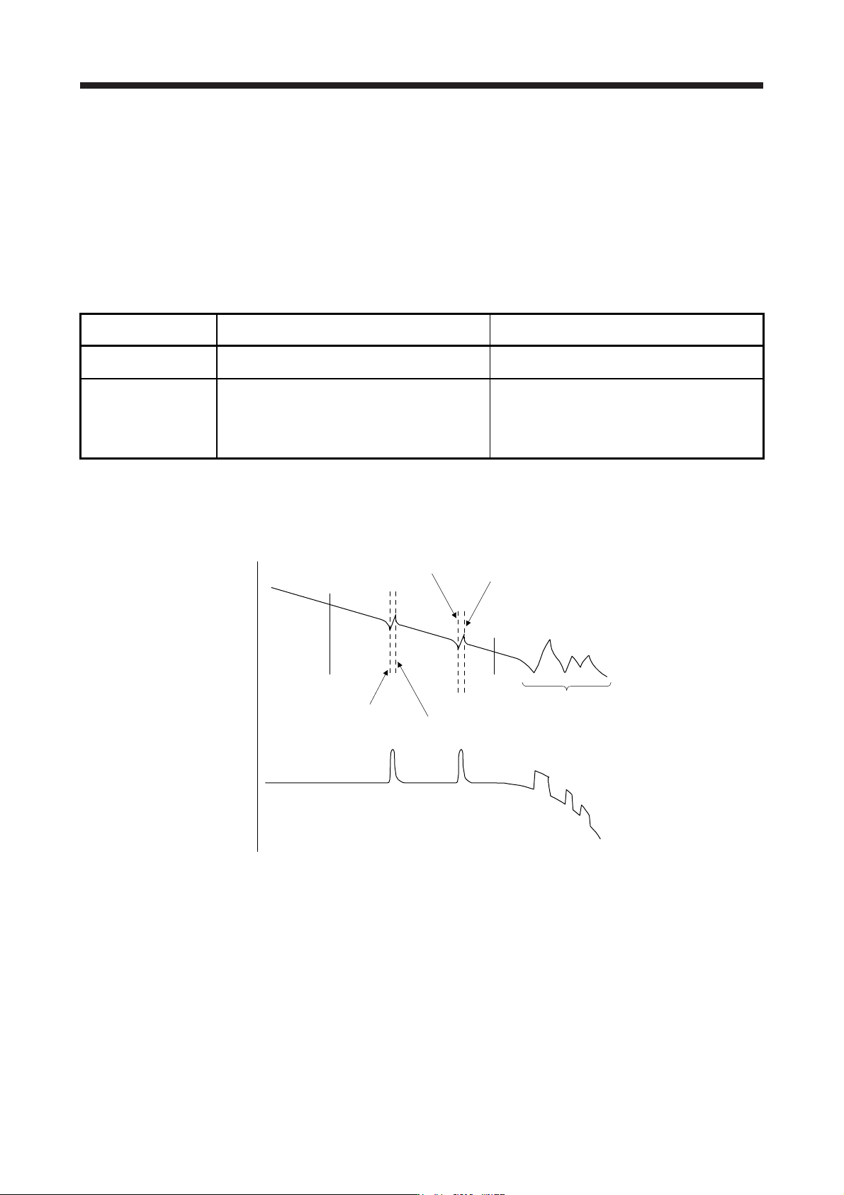
(a) When a vibration peak can be confirmed with machine analyzer using MR Configurator2, or external
equipment.
1 Hz
Gain characteristics
Phase
-90 degrees
300 Hz
Vibration suppression control 1 -
Vibration frequency
(anti-resonance frequency)
[Pr. PB19]
Vibration suppression control 1 -
Resonance frequency
[Pr. PB20]
Vibration suppression control 2 -
Vibration frequency
(anti-resonance frequency)
[Pr. PB52]
Vibration suppression control 2 -
Resonance frequency
[Pr. PB53]
Resonance of more than
300 Hz is not the target of control.
7. SPECIAL ADJUSTMENT FUNCTIONS
7 - 13
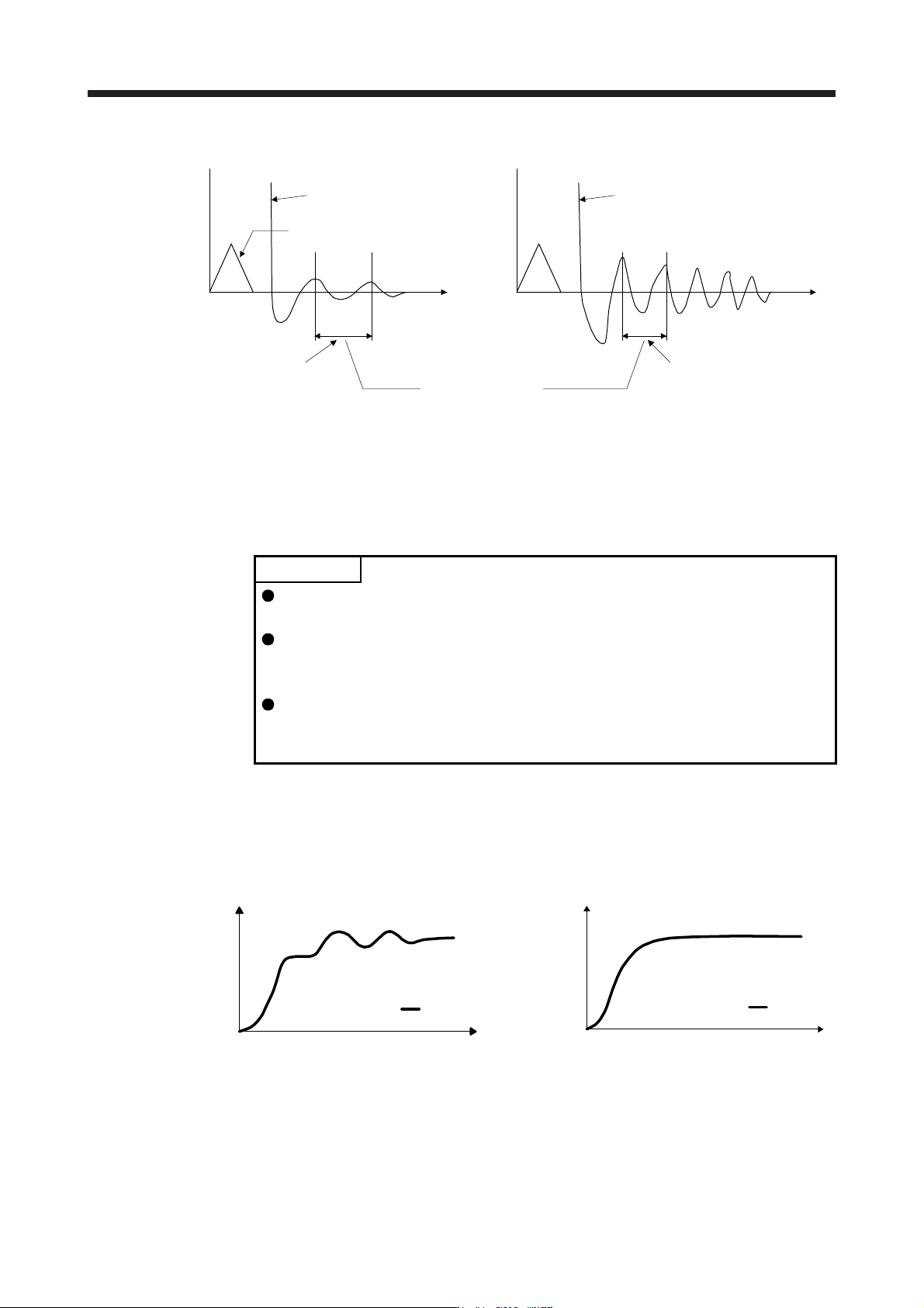
(b) When vibration can be confirmed using monitor signal or external sensor
t
Motor-side vibration
(droop pulses)
Position command frequency
t
External acceleration pickup signal, etc.
Vibration suppression control -
Vibration frequency
Vibration suppression control -
Resonance frequency
Set the same value.
Vibration cycle [Hz] Vibration cycle [Hz]
Step 3 Fine-adjust "Vibration suppression control - Vibration frequency damping" and "Vibration
suppression control - Resonance frequency damping".
7.1.6 Command notch filter
POINT
By using the advanced vibration suppression control II and the command notch
filter, the load-side vibration of three frequencies can be suppressed.
The frequency range of machine vibration, which can be supported by the
command notch filter, is between 4.5 Hz and 2250 Hz. Set a frequency close to
the machine vibration frequency and within the range.
When [Pr. PB45 Command notch filter] is changed during the positioning
operation, the changed setting is not reflected. The setting is reflected
approximately 150 ms after the servo motor stops (after servo-lock).
(1) Function
Command notch filter has a function that lowers the gain of the specified frequency contained in a
position command. By lowering the gain, load-side vibration, such as work-side vibration and base
shake, can be suppressed. Which frequency to lower the gain and how deep to lower the gain can be
set.
Position
Load side
t
Command notch filter: disabled
Load side
t
Position
Command notch filter: enabled
7. SPECIAL ADJUSTMENT FUNCTIONS
7 - 14
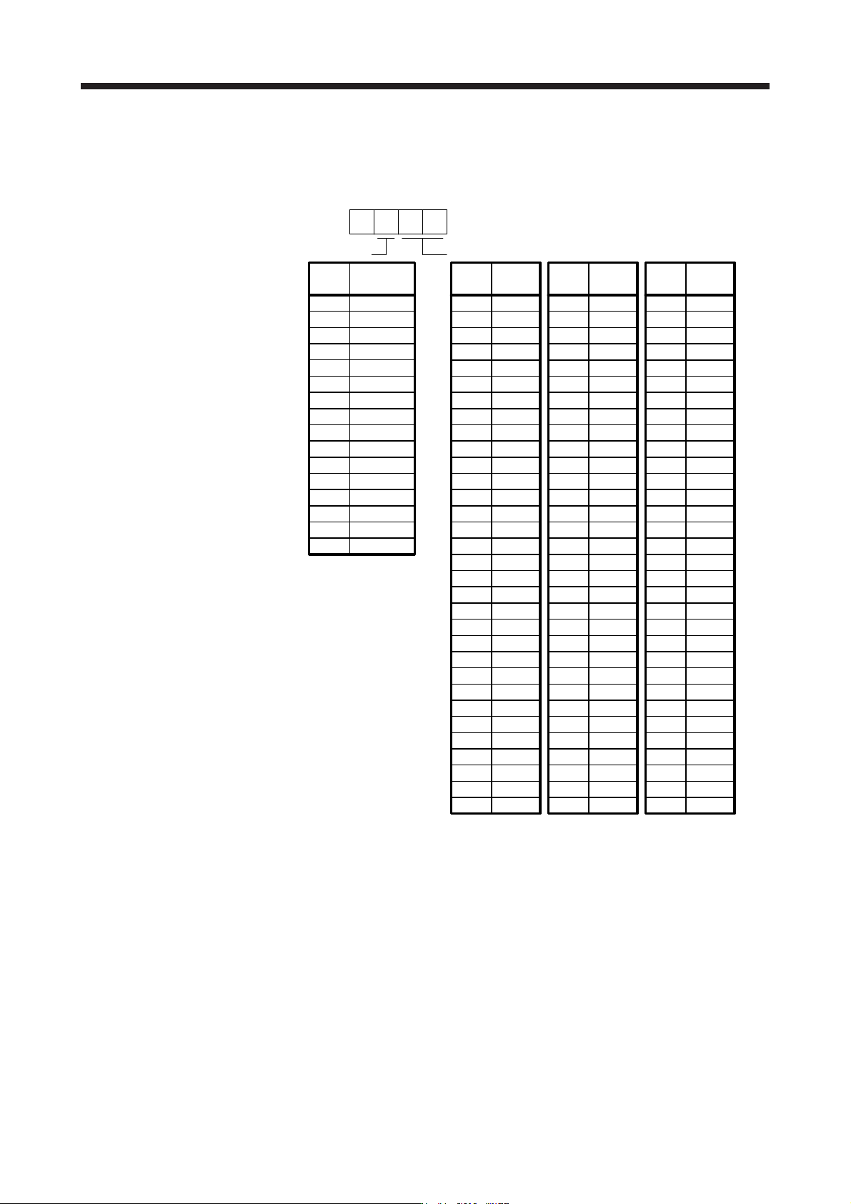
(2) Parameter
Set [Pr. PB45 Command notch filter] as shown below. For the command notch filter setting frequency,
set the closest value to the vibration frequency [Hz] at the load side.
Setting
value
Command notch filter setting frequency
Setting
value
Frequency
[Hz]
00
01
02
03
0
Frequency
[Hz]
Setting
value
Frequency
[Hz]
04
05
06
07
08
09
0A
0B
0C
0D
0E
0F
10
11
12
13
14
15
16
17
18
19
1A
1B
1C
1D
1E
1F
20
21
22
23
24
25
26
27
28
29
2A
2B
2C
2D
2E
2F
30
31
32
33
34
35
36
37
38
39
3A
3B
3C
3D
3E
3F
40
41
42
43
44
45
46
47
48
49
4A
4B
4C
4D
4E
4F
50
51
52
53
54
55
56
57
58
59
5A
5B
5C
5D
5E
5F
Disabled
2250
1125
750
562
450
375
321
281
250
225
204
187
173
160
150
140
132
125
118
112
107
102
97
93
90
86
83
80
77
75
72
70
66
62
59
56
53
51
48
46
45
43
41
40
38
37
36
35.2
33.1
31.3
29.6
28.1
26.8
25.6
24.5
23.4
22.5
21.6
20.8
20.1
19.4
18.8
18.2
17.6
16.5
15.6
14.8
14.1
13.4
12.8
12.2
11.7
11.3
10.8
10.4
10.0
9.7
9.4
9.1
8.8
8.3
7.8
7.4
7.0
6.7
6.4
6.1
5.9
5.6
5.4
5.2
5.0
4.9
4.7
4.5
Notch depth
0
1
2
3
4
5
6
7
8
9
A
B
C
D
E
F
Setting
value
Depth
[dB]
[Pr. PB45]
-40.0
-24.1
-18.1
-14.5
-12.0
-10.1
-8.5
-7.2
-6.0
-5.0
-4.1
-3.3
-2.5
-1.8
-1.2
-0.6