sh030106u.pdf - 第251页
7. SPEC IAL ADJUSTMEN T FUNCT IONS 7 - 22 (b) Switch ing timi ng char t After-switching gain 63.4% CDT = 100 ms Before-switching gain Gain switching Droop pulses [pulse] +CDL -CDL 0 Command pulses Droop pulses Command pu…
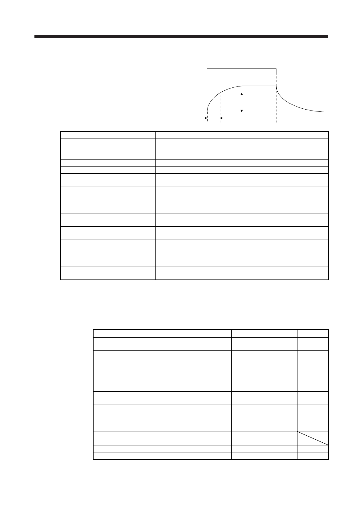
7. SPECIAL ADJUSTMENT FUNCTIONS
7 - 21
(b) Switching timing chart
After-switching gain
63.4%
CDT = 100 ms
Before-switching gain
Gain switching
Control command
from controller
OFF
ON
OFF
Model loop gain 100 → 50 → 100
Load to motor inertia ratio/load to motor
mass ratio
4.00 → 10.00 → 4.00
Position loop gain 120 → 84 → 120
Speed loop gain 3000 → 4000 → 3000
Speed integral compensation 20 → 50 → 20
Vibration suppression control 1 - Vibration
frequency
50 → 60 → 50
Vibration suppression control 1 -
Resonance frequency
50 → 60 → 50
Vibration suppression control 1 - Vibration
frequency damping
0.20 → 0.15 → 0.20
Vibration suppression control 1 -
Resonance frequency damping
0.20 → 0.15 → 0.20
Vibration suppression control 2 - Vibration
frequency
20 → 30 → 20
Vibration suppression control 2 -
Resonance frequency
20 → 30 → 20
Vibration suppression control 2 - Vibration
frequency damping
0.10 → 0.05 → 0.10
Vibration suppression control 2 -
Resonance frequency damping
0.10 → 0.05 → 0.10
(2) When you choose switching by droop pulses
The vibration suppression control after gain switching and model loop gain after gain switching cannot
be used.
(a) Setting example
Parameter Symbol Name Setting value Unit
PB06 GD2
Load to motor inertia ratio/load to
motor mass ratio
4.00 [Multiplier]
PB08 PG2 Position loop gain 120 [rad/s]
PB09 VG2 Speed loop gain 3000 [rad/s]
PB10 VIC Speed integral compensation 20 [ms]
PB29 GD2B
Load to motor inertia ratio/load to
motor mass ratio after gain
switching
10.00 [Multiplier]
PB30 PG2B
Position loop gain after gain
switching
84 [rad/s]
PB31 VG2B
Speed loop gain after gain
switching
4000 [rad/s]
PB32 VICB
Speed integral compensation after
gain switching
50 [ms]
PB26 CDP Gain switching selection 0003
(switching by droop pulses)
PB27 CDL Gain switching condition 50 [pulse]
PB28 CDT Gain switching time constant 100 [ms]
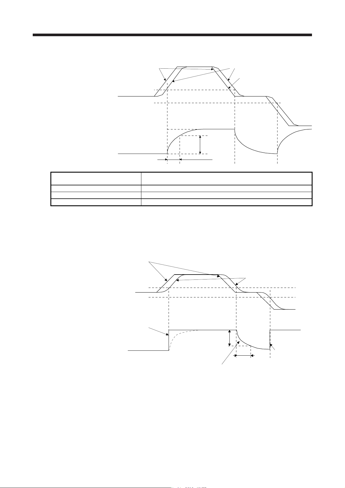
7. SPECIAL ADJUSTMENT FUNCTIONS
7 - 22
(b) Switching timing chart
After-switching gain
63.4%
CDT = 100 ms
Before-switching gain
Gain switching
Droop pulses
[pulse]
+CDL
-CDL
0
Command pulses
Droop pulses
Command pulses
Load to motor inertia ratio/load to motor
mass ratio
4.00 → 10.00 → 4.00 → 10.00
Position loop gain 120 → 84 → 120 → 84
Speed loop gain 3000 → 4000 → 3000 → 4000
Speed integral compensation 20 → 50 → 20 → 50
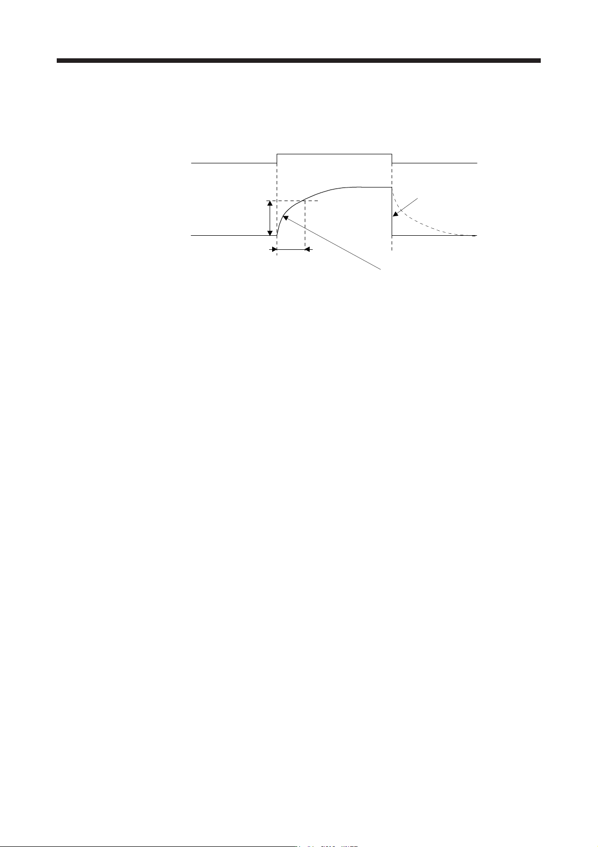
(3) When the gain switching time constant is disabled
(a) Switching time constant disabled was selected.
The gain switching time constant is disabled. The time constant is enabled at gain return.
The following example shows for [Pr. PB26 (CDP)] = 0103, [Pr. PB27 (CDL)] = 100 [pulse], and [Pr.
PB28 (CDT)] = 100 [ms].
Command pulses
Droop pulses
+100 pulses
-100 pulses
0Droop pulses [pulse]
Switching time constant
disabled
Switching at 0 ms
After-switching gain
Before-switching gain
Switching at [Pr. PB28 (CDT)] = 100 [ms] only when gain switching off (when returning)
CDT = 100 ms
63.4%
Switching at 0 ms
After-switching gain
Gain switching
7. SPECIAL ADJUSTMENT FUNCTIONS
7 - 23
(b) Return time constant disabled was selected.
The gain switching time constant is enabled. The time constant is disabled at gain return.
The following example shows for [Pr. PB26 (CDP)] = 0201, [Pr. PB27 (CDL)] = 0, and [Pr. PB28
(CDT)] = 100 [ms].
ONCDP (Gain switching)
After-switching gain
Before-switching gain
Switching at [Pr. PB28 (CDT)] = 100 [ms] only when gain switching on (when switching)
CDT = 100 ms
Return time constant disabled
Switching at 0 ms
OFF OFF
63.4%
Gain switching