sh030106u.pdf - 第255页
7. SPEC IAL ADJUSTMEN T FUNCT IONS 7 - 26 7.3.2 Insta ntaneous power failure t ough driv e funct ion The instant aneous power f ailure to ugh dr ive func tion av oids [ AL . 10 U ndervolta ge] ev en whe n an instantan eo…
7. SPECIAL ADJUSTMENT FUNCTIONS
7 - 25
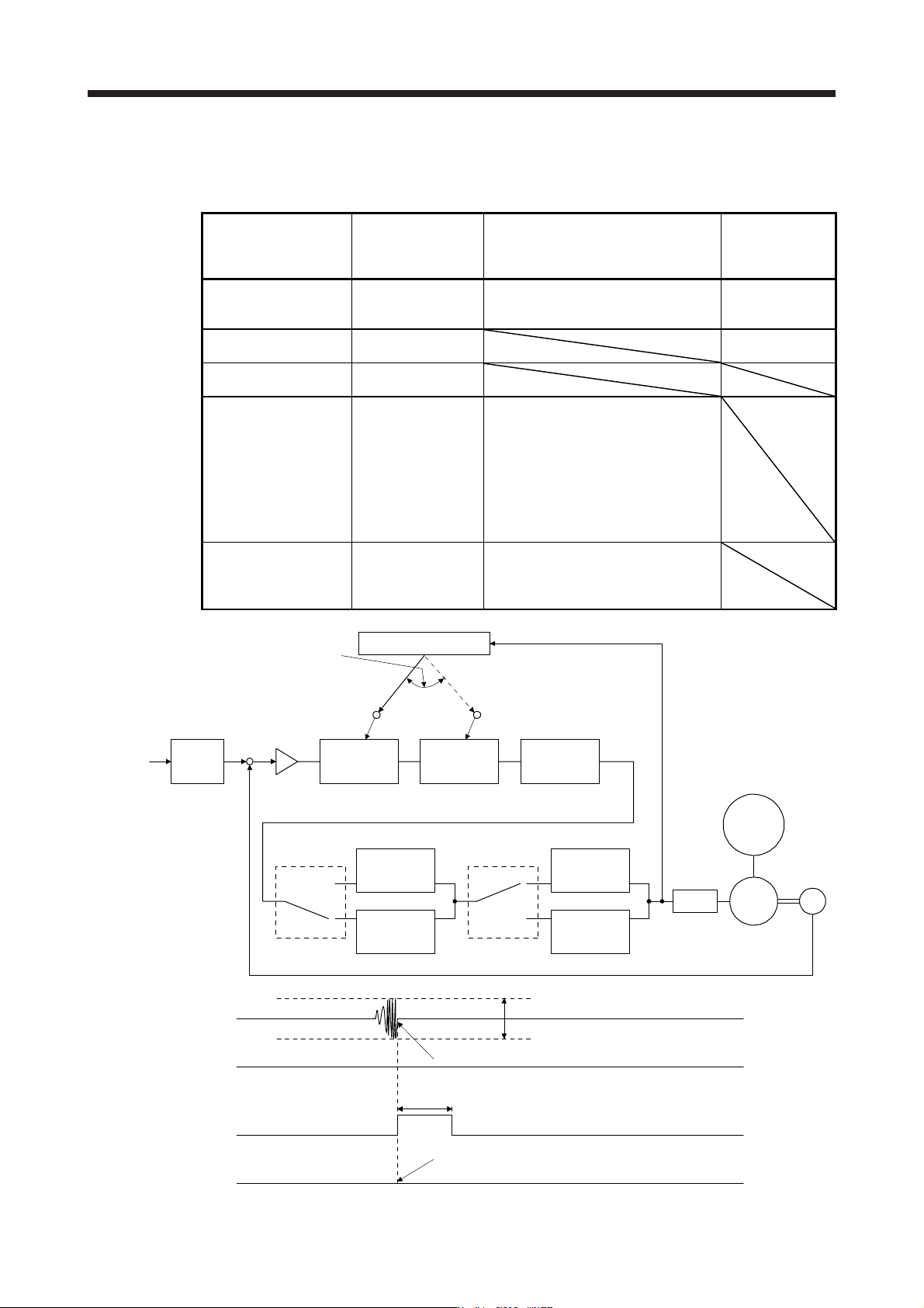
The following shows the function block diagram of the vibration tough drive function.
The function detects machine resonance frequency and compare it with [Pr. PB13] and [Pr. PB15], and reset
a machine resonance frequency of a parameter whose set value is closer.
Filter Setting parameter Precaution
Parameter that is
reset with vibration
tough drive
function
Machine resonance
suppression filter 1
PB01/PB13/PB14
The filter can be set automatically with
"Filter tuning mode selection" in [Pr.
PB01].
PB13
Machine resonance
suppression filter 2
PB15/PB16 PB15
Machine resonance
suppression filter 3
PB46/PB47
Machine resonance
suppression filter 4
PB48/PB49
Enabling the machine resonance
suppression filter 4 disables the shaft
resonance suppression filter.
Using the shaft resonance suppression
filter is recommended because it is
adjusted properly depending on the
usage situation.
The shaft resonance suppression filter is
enabled for the initial setting.
Machine resonance
suppression filter 5
PB50/PB51
Enabling the robust filter disables the
machine resonance suppression filter 5.
The robust filter is disabled for the initial
setting.
Command
pulse train
Command
filter
Encoder
Servo motor
PWM
M
Load
+
-
Machine
resonance
suppression
filter 1
[Pr. PB13] [Pr. PB15] [Pr. PB46]
Machine
resonance
suppression
filter 2
Machine
resonance
suppression
filter 3
Machine
resonance
suppression
filter 4
Machine
resonance
suppression
filter 5
Shaft
resonance
suppression
filter
Robust filter
[Pr. PB48]
[Pr. PB50]
[Pr. PB17]
[Pr. PB49] [Pr. PE41]
Updates the parameter
whose setting is the
closest to the machine
resonance frequency.
Vibration tough drive
Torque
ALM
(Malfunction)
WNG
(Warning)
MTTR
(During tough drive)
ON
OFF
[Pr. PF23 Vibration tough drive - Oscillation detection level]
Detects the machine resonance and reconfigures the filter automatically.
During tough drive (MTTR) is not turned on in the vibration tough drive function.
ON
OFF
ON
OFF
5 s

7. SPECIAL ADJUSTMENT FUNCTIONS
7 - 26
7.3.2 Instantaneous power failure tough drive function
The instantaneous power failure tough drive function avoids [AL. 10 Undervoltage] even when an
instantaneous power failure occurs during operation. When the instantaneous power failure tough drive
activates, the function will increase the tolerance against instantaneous power failure using the electrical
energy charged in the capacitor in the servo amplifier and will change an alarm level of [AL. 10
Undervoltage] simultaneously. The [AL. 10.1 Voltage drop in the control circuit power] detection time for the
control circuit power supply can be changed by [Pr. PF25 SEMI-F47 function - Instantaneous power failure
detection time]. In addition, [AL. 10.2 Voltage drop in the main circuit power] detection level for the bus
voltage is changed automatically.
POINT
MBR (Electromagnetic brake interlock) will not turn off during the instantaneous
power failure tough drive.
When selecting "Enabled (_ _ _ 1)" for "Torque limit function selection at
instantaneous power failure" in [Pr. PA26], if an instantaneous power failure
occurs during operation, you can save electric energy charged in the capacitor in
the servo amplifier by limiting torque at acceleration. You can also delay the time
until the occurrence of [AL. 10.2 Voltage drop in the main circuit power]. Doing
this will enable you to set a longer time in [Pr. PF25 SEMI-F47 function -
Instantaneous power failure detection time].
When the load of instantaneous power failure is large, [AL. 10.2] caused by the
bus voltage drop may occur regardless of the set value of [Pr. PF25 SEMI-F47
function - Instantaneous power failure detection time].
The external dynamic brake cannot be used for compliance with SEMI-F47
standard. Do not assign DB (Dynamic brake interlock) in [Pr. PD07] to [Pr.
PD09]. Failure to do so will cause the servo amplifier to become servo-off when
an instantaneous power failure occurs.
The setting range of [Pr. PF25 SEMI-F47 function - Instantaneous power failure
detection time] differs depending on the software version of the servo amplifier
as follows.
Software version C0 or later: Setting range 30 ms to 200 ms
Software version C1 or earlier: Setting range 30 ms to 500 ms
To comply with SEMI-F47 standard, it is unnecessary to change the initial value
(200 ms).
When the instantaneous power failure time exceeds 200 ms, and if the
instantaneous power failure voltage is less than 70 % of the rated input voltage,
the power may be turned off normally even if a value larger than 200 ms is set in
the parameter.
7. SPECIAL ADJUSTMENT FUNCTIONS
7 - 27
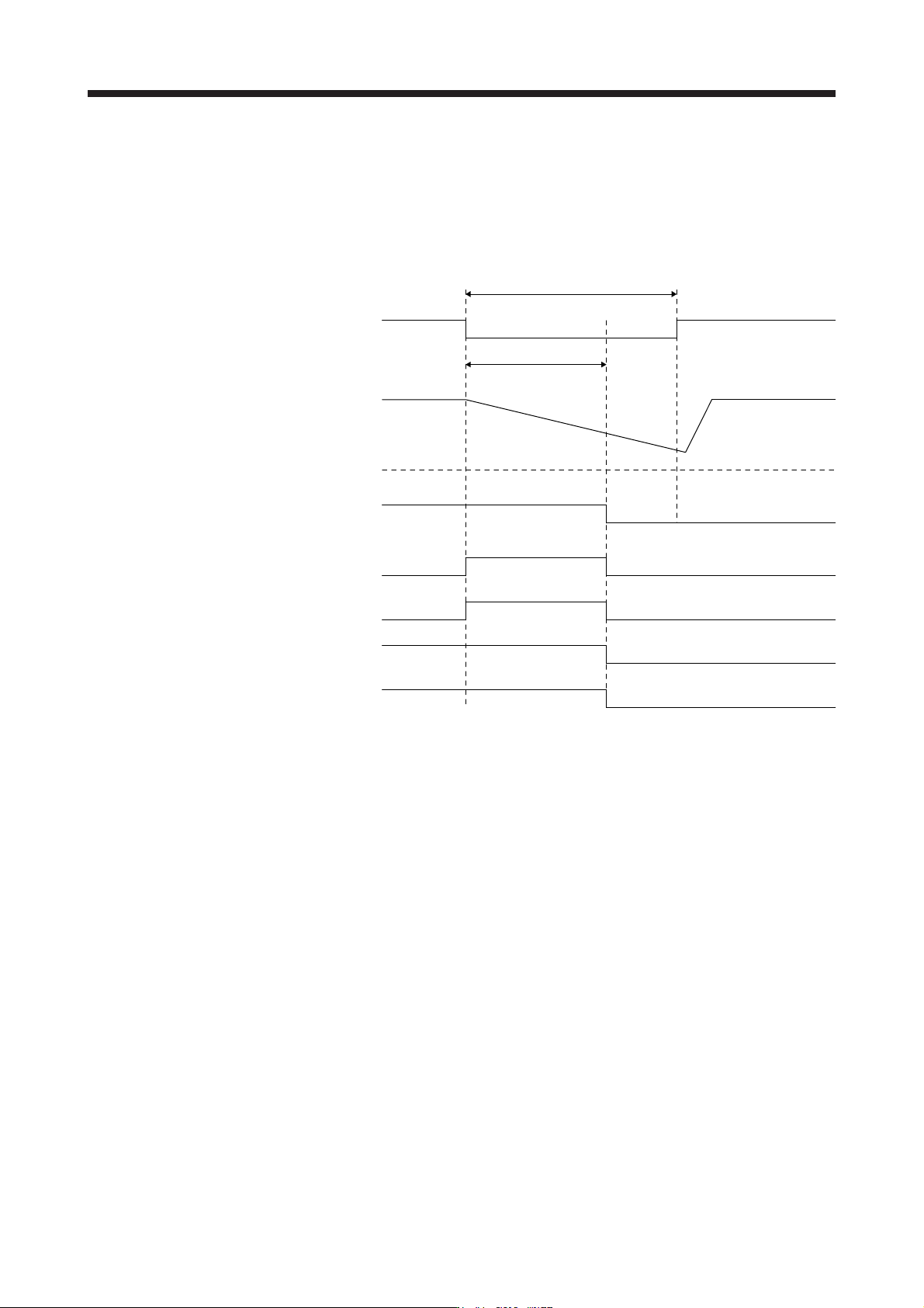
(1) Instantaneous power failure time of the control circuit power supply > [Pr. PF25 SEMI-F47 function -
Instantaneous power failure detection time]
The alarm occurs when the instantaneous power failure time of the control circuit power supply exceeds
[Pr. PF25 SEMI-F47 function - Instantaneous power failure detection time].
MTTR (During tough drive) turns on after detecting the instantaneous power failure.
MBR (Electromagnetic brake interlock) turns off when the alarm occurs.
Control circuit
power supply
Bus voltage
Undervoltage level
(Note)
A
LM
(Malfunction)
[Pr. PF25]
Instantaneous power failure time of the control circuit power supply
MTTR
(During tough drive)
MBR
(Electromagnetic
brake interlock)
Base circuit
ON
OFF
ON (energization)
OFF (power failure)
ON
OFF
W
NG
(Warning)
ON
OFF
ON
OFF
ON
OFF
Note. Refer to table 7.1 for the undervolta
g
e level.