sh030106u.pdf - 第257页
7. SPEC IAL ADJUSTMEN T FUNCT IONS 7 - 28 (2) Instantaneous po wer fail ure time of th e control c ircuit power s upply < [ Pr. PF25 SEMI-F47 fu nction - Instantane ous po wer fail ure detec tion t ime] Operation s ta…
7. SPECIAL ADJUSTMENT FUNCTIONS
7 - 27
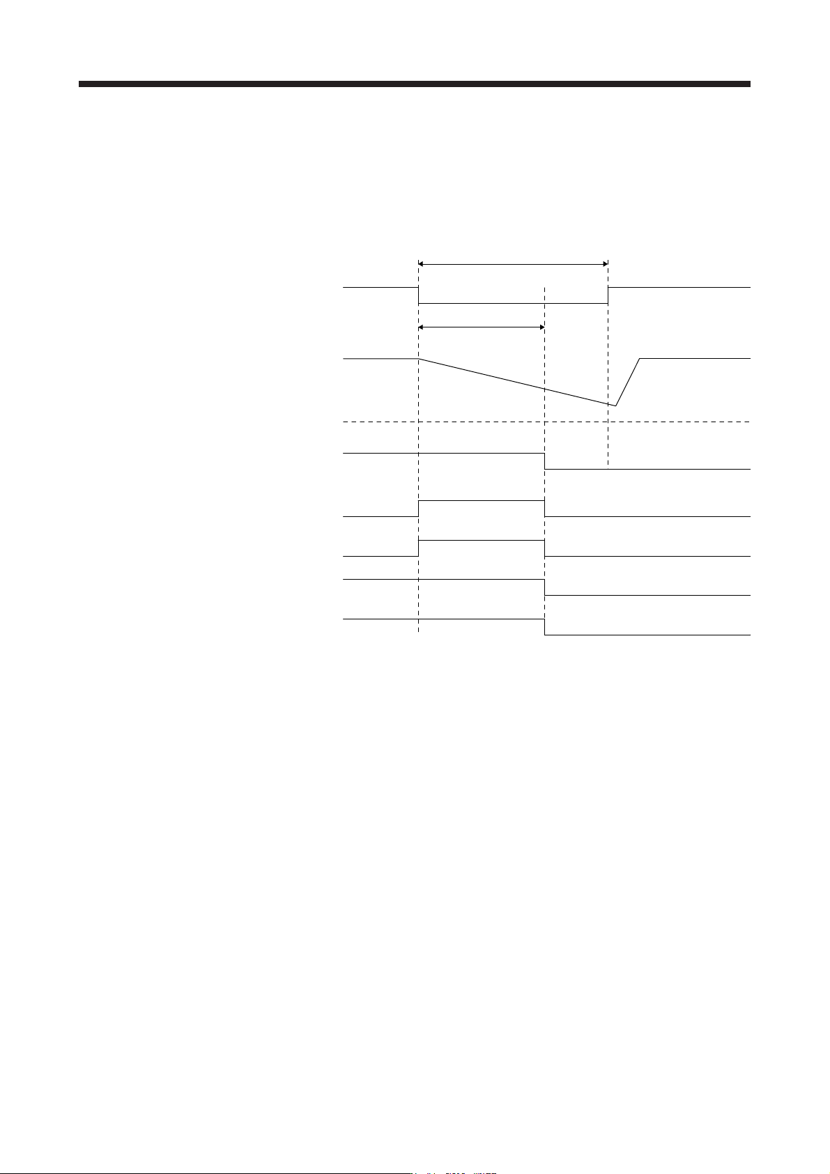
(1) Instantaneous power failure time of the control circuit power supply > [Pr. PF25 SEMI-F47 function -
Instantaneous power failure detection time]
The alarm occurs when the instantaneous power failure time of the control circuit power supply exceeds
[Pr. PF25 SEMI-F47 function - Instantaneous power failure detection time].
MTTR (During tough drive) turns on after detecting the instantaneous power failure.
MBR (Electromagnetic brake interlock) turns off when the alarm occurs.
Control circuit
power supply
Bus voltage
Undervoltage level
(Note)
A
LM
(Malfunction)
[Pr. PF25]
Instantaneous power failure time of the control circuit power supply
MTTR
(During tough drive)
MBR
(Electromagnetic
brake interlock)
Base circuit
ON
OFF
ON (energization)
OFF (power failure)
ON
OFF
W
NG
(Warning)
ON
OFF
ON
OFF
ON
OFF
Note. Refer to table 7.1 for the undervolta
g
e level.
7. SPECIAL ADJUSTMENT FUNCTIONS
7 - 28
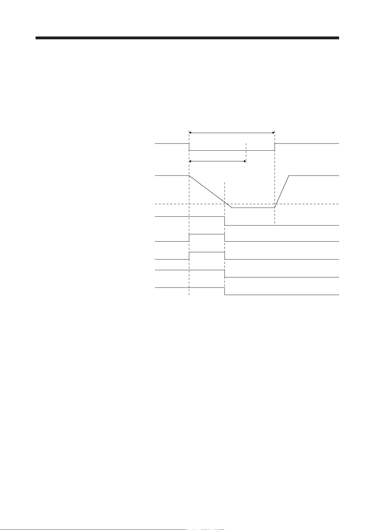
(2) Instantaneous power failure time of the control circuit power supply < [Pr. PF25 SEMI-F47 function -
Instantaneous power failure detection time]
Operation status differs depending on how bus voltage decrease.
(a) When the bus voltage decrease lower than Undervoltage level within the instantaneous power failure
time of the control circuit power supply
[AL. 10 Undervoltage] occurs when the bus voltage decrease lower than Undervoltage level
regardless of the enabled instantaneous power failure tough drive.
[Pr. PF25]
Instantaneous power failure time of the control circuit power supply
ON
OFF
ON
OFF
ON
OFF
ON
OFF
ON
OFF
Control circuit
power suppl
y
Bus voltage
Undervoltage level
(Note)
A
LM
(Malfunction)
MTTR
(During tough drive)
MBR
(Electromagnetic
brake interlock)
Base circuit
W
NG
(Warning)
ON (energization)
OFF (power failure)
Note. Refer to table 7.1 for the undervolta
g
e level.
7. SPECIAL ADJUSTMENT FUNCTIONS
7 - 29
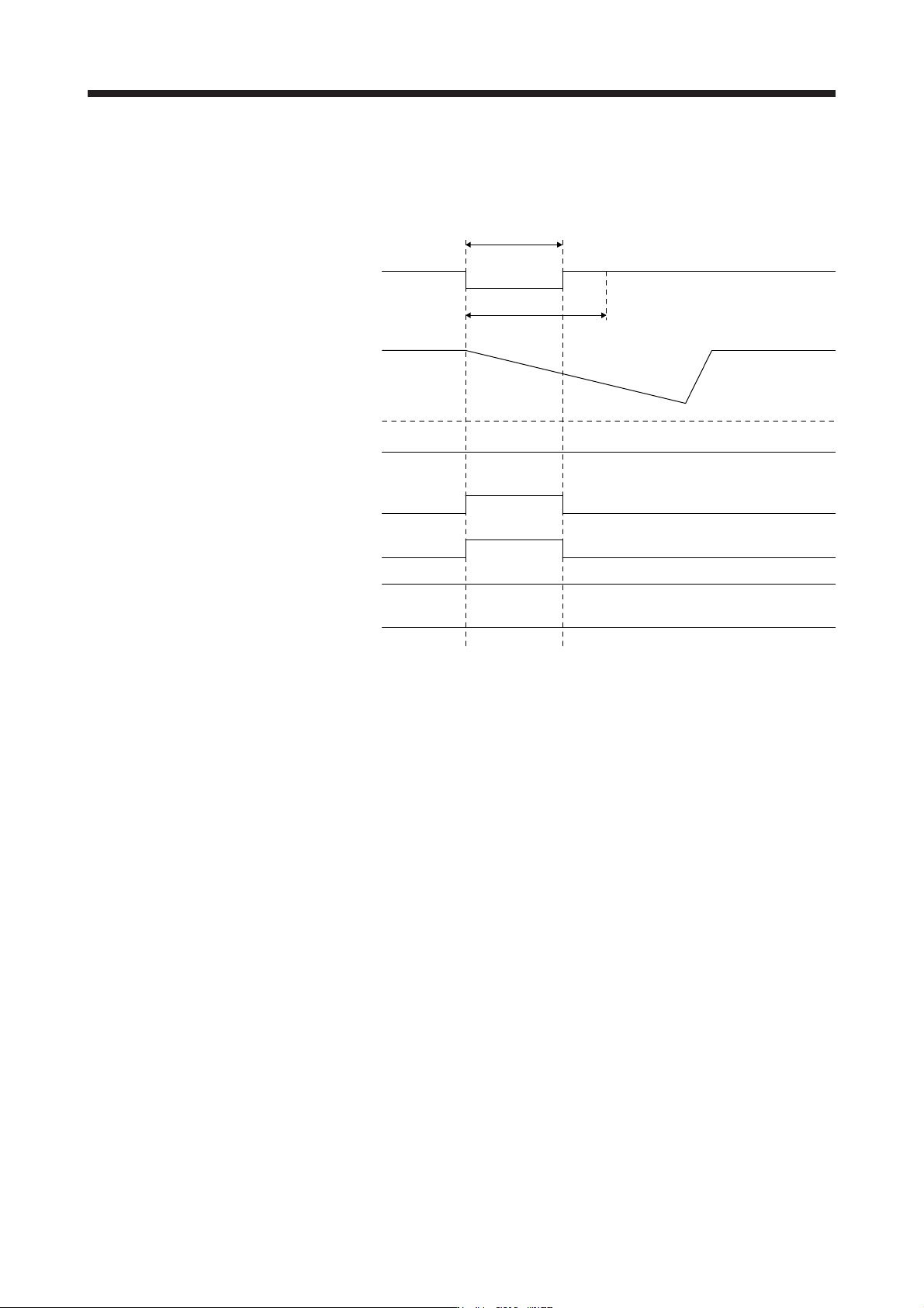
(b) When the bus voltage does not decrease lower than Undervoltage level within the instantaneous
power failure time of the control circuit power supply
The operation continues without alarming.
Control circuit
power suppl
y
Bus voltage
Undervoltage level
(Note)
A
LM
(Malfunction)
MTTR
(During tough drive)
MBR
(Electromagnetic
brake interlock)
Base circuit
W
NG
(Warning)
[Pr. PF25]
Instantaneous power failure time of the
control circuit power supply
ON
OFF
ON
OFF
ON
OFF
ON
OFF
ON
OFF
ON (energization)
OFF (power failure)
Note. Refer to table 7.1 for the undervolta
g
e level.