sh030106u.pdf - 第260页
7. SPEC IAL ADJUSTMEN T FUNCT IONS 7 - 31 (2) Requirem ents c onditions of SEMI-F 47 st andard Table 7.2 shows th e permis sible time of i nstant aneous power fai lure f or inst antane ous power failur e of SEMI-F47 s ta…
7. SPECIAL ADJUSTMENT FUNCTIONS
7 - 30
7.4 Compliance with SEMI-F47 standard
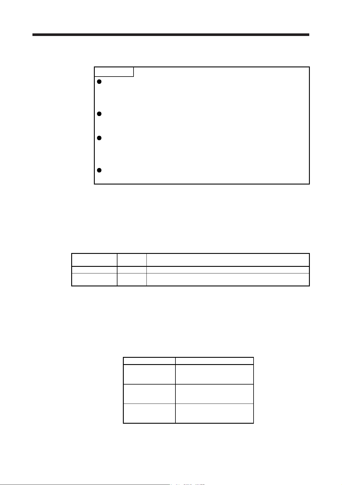
POINT
The control circuit power supply of the servo amplifier can be possible to comply
with SEMI-F47 standard. However, a back-up capacitor may be necessary for
instantaneous power failure in the main circuit power supply depending on the
power supply impedance and operating situation.
Use a 3-phase for the input power supply of the servo amplifier. Using a 1-phase
100 V AC/200 V AC for the input power supply will not comply with SEMI-F47
standard.
The external dynamic brake cannot be used for compliance with SEMI-F47
standard. Do not assign DB (Dynamic brake interlock) in [Pr. PD07] to [Pr.
PD09]. Failure to do so will cause the servo amplifier to become servo-off when
an instantaneous power failure occurs.
Be sure to perform actual machine tests and detail checks for power supply
instantaneous power failure of SEMI-F47 standard with your equipment.
The following explains the compliance with "SEMI-F47 semiconductor process equipment voltage sag
immunity test" of MR-J4 series.
This function enables to avoid triggering [AL. 10 Undervoltage] using the electrical energy charged in the
capacitor in case that an instantaneous power failure occurs during operation.
(1) Parameter setting
Setting [Pr. PA20] and [Pr. PF25] as follows will enable SEMI-F47 function.
Parameter
Setting
value
Description
PA20 _ 1 _ _ Enable SEMI-F47 function selection.
PF25 200
Set the time [ms] of the [AL. 10.1 Voltage drop in the control circuit power]
occurrence.
Enabling SEMI-F47 function will change operation as follows.
(a) The voltage will drop in the control circuit power with "Rated voltage × 50% or less". 200 ms later,
[AL. 10.1 Voltage drop in the control circuit power] will occur.
(b) [AL. 10.2 Voltage drop in the main circuit power] will occur when bus voltage is as follows.
Table 7.1 Voltages which trigger [AL. 10.2 Voltage drop in the main circuit power]
Servo amplifier Bus voltage which triggers alarm
MR-J4-10B(-RJ)
to
MR-J4-700B(-RJ)
158 V DC
MR-J4-11KB(-RJ)
to
MR-J4-22KB(-RJ)
200 V DC
MR-J4-60B4(-RJ)
to
MR-J4-22KB4(-RJ)
380 V DC
(c) MBR (Electromagnetic brake interlock) will turn off when [AL. 10.1 Voltage drop in the control circuit
power] occurs.
7. SPECIAL ADJUSTMENT FUNCTIONS
7 - 31
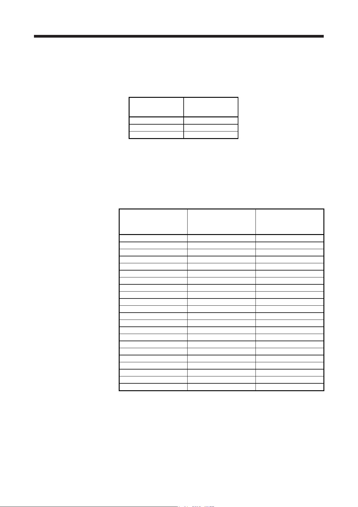
(2) Requirements conditions of SEMI-F47 standard
Table 7.2 shows the permissible time of instantaneous power failure for instantaneous power failure of
SEMI-F47 standard.
Table 7.2 Requirements conditions of SEMI-F47 standard
Instantaneous power
failure voltage
Permissible time of
instantaneous power
failure [s]
Rated voltage × 80% 1
Rated voltage × 70% 0.5
Rated voltage × 50% 0.2
(3) Calculation of tolerance against instantaneous power failure
Table 7.3 shows tolerance against instantaneous power failure when instantaneous power failure
voltage is "rated voltage × 50%" and instantaneous power failure time is 200 ms.
Table 7.3 Tolerance against instantaneous power failure
(instantaneous power failure voltage = rated voltage × 50%,
instantaneous power failure time = 200 ms)
Servo amplifier
Instantaneous maximum
output [W]
Tolerance against
instantaneous
power failure [W]
(voltage drop between lines)
MR-J4-10B(-RJ) 350 250
MR-J4-20B(-RJ) 700 420
MR-J4-40B(-RJ) 1400 630
MR-J4-60B(-RJ) 2100 410
MR-J4-70B(-RJ) 2625 1150
MR-J4-100B(-RJ) 3000 1190
MR-J4-200B(-RJ) 5400 2040
MR-J4-350B(-RJ) 10500 2600
MR-J4-500B(-RJ) 15000 4100
MR-J4-700B(-RJ) 21000 5900
MR-J4-11KB(-RJ) 40000 2600
MR-J4-15KB(-RJ) 50000 3500
MR-J4-22KB(-RJ) 56000 4300
MR-J4-60B4(-RJ) 1900 190
MR-J4-100B4(-RJ) 3500 200
MR-J4-200B4(-RJ) 5400 350
MR-J4-350B4(-RJ) 10500 730
MR-J4-500B4(-RJ) 15000 890
MR-J4-700B4(-RJ) 21000 1500
MR-J4-11KB4(-RJ) 40000 2400
MR-J4-15KB4(-RJ) 50000 3200
MR-J4-22KB4(-RJ) 56000 4200

7. SPECIAL ADJUSTMENT FUNCTIONS
7 - 32
Instantaneous maximum output means power which servo amplifier can output in maximum torque at
rated speed. You can examine margins to compare the values of following conditions and instantaneous
maximum output.
Even if driving at maximum torque with low speed in actual operation, the motor will not drive with the
maximum output. This can be handled as a margin.
The following shows the conditions of tolerance against instantaneous power failure.
(a) Delta connection
For the 3-phase (L1/L2/L3) delta connection, an instantaneous power failure occurs in the voltage
between a pair of lines (e.g. between L1 and L2) among voltages between three pairs of lines
(between L1 and L2, L2 and L3, or L3 and L1).
(b) Star connection
For the 3-phase (L1/L2/L3/neutral point N) star connection, an instantaneous power failure occurs in
the voltage between a pair of lines (e.g. between L1 and N) among voltages at six locations,
between three pairs of lines (between L1 and L2, L2 and L3, or L3 and L1) and between one of the
lines and the neutral point (between L1 and N, L2 and N, or L3 and N).