sh030106u.pdf - 第261页
7. SPEC IAL ADJUSTMEN T FUNCT IONS 7 - 32 Instantane ous max imum o utput me ans power which s erv o amplifier can ou tput in maximum torqu e at rated spe ed. You c an exam ine mar gins to compar e the values of followi …
7. SPECIAL ADJUSTMENT FUNCTIONS
7 - 31
(2) Requirements conditions of SEMI-F47 standard
Table 7.2 shows the permissible time of instantaneous power failure for instantaneous power failure of
SEMI-F47 standard.
Table 7.2 Requirements conditions of SEMI-F47 standard
Instantaneous power
failure voltage
Permissible time of
instantaneous power
failure [s]
Rated voltage × 80% 1
Rated voltage × 70% 0.5
Rated voltage × 50% 0.2
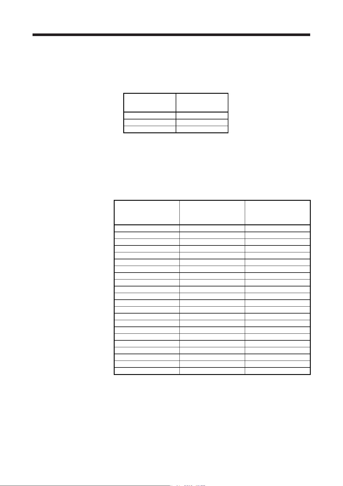
(3) Calculation of tolerance against instantaneous power failure
Table 7.3 shows tolerance against instantaneous power failure when instantaneous power failure
voltage is "rated voltage × 50%" and instantaneous power failure time is 200 ms.
Table 7.3 Tolerance against instantaneous power failure
(instantaneous power failure voltage = rated voltage × 50%,
instantaneous power failure time = 200 ms)
Servo amplifier
Instantaneous maximum
output [W]
Tolerance against
instantaneous
power failure [W]
(voltage drop between lines)
MR-J4-10B(-RJ) 350 250
MR-J4-20B(-RJ) 700 420
MR-J4-40B(-RJ) 1400 630
MR-J4-60B(-RJ) 2100 410
MR-J4-70B(-RJ) 2625 1150
MR-J4-100B(-RJ) 3000 1190
MR-J4-200B(-RJ) 5400 2040
MR-J4-350B(-RJ) 10500 2600
MR-J4-500B(-RJ) 15000 4100
MR-J4-700B(-RJ) 21000 5900
MR-J4-11KB(-RJ) 40000 2600
MR-J4-15KB(-RJ) 50000 3500
MR-J4-22KB(-RJ) 56000 4300
MR-J4-60B4(-RJ) 1900 190
MR-J4-100B4(-RJ) 3500 200
MR-J4-200B4(-RJ) 5400 350
MR-J4-350B4(-RJ) 10500 730
MR-J4-500B4(-RJ) 15000 890
MR-J4-700B4(-RJ) 21000 1500
MR-J4-11KB4(-RJ) 40000 2400
MR-J4-15KB4(-RJ) 50000 3200
MR-J4-22KB4(-RJ) 56000 4200

7. SPECIAL ADJUSTMENT FUNCTIONS
7 - 32
Instantaneous maximum output means power which servo amplifier can output in maximum torque at
rated speed. You can examine margins to compare the values of following conditions and instantaneous
maximum output.
Even if driving at maximum torque with low speed in actual operation, the motor will not drive with the
maximum output. This can be handled as a margin.
The following shows the conditions of tolerance against instantaneous power failure.
(a) Delta connection
For the 3-phase (L1/L2/L3) delta connection, an instantaneous power failure occurs in the voltage
between a pair of lines (e.g. between L1 and L2) among voltages between three pairs of lines
(between L1 and L2, L2 and L3, or L3 and L1).
(b) Star connection
For the 3-phase (L1/L2/L3/neutral point N) star connection, an instantaneous power failure occurs in
the voltage between a pair of lines (e.g. between L1 and N) among voltages at six locations,
between three pairs of lines (between L1 and L2, L2 and L3, or L3 and L1) and between one of the
lines and the neutral point (between L1 and N, L2 and N, or L3 and N).
7. SPECIAL ADJUSTMENT FUNCTIONS
7 - 33
7.5 Model adaptive control disabled
POINT
Change the parameters while the servo motor stops.
When setting auto tuning response ([Pr. PA09]), change the setting value one by
one to adjust it while checking operation status of the servo motor.
This is used with servo amplifiers with software version B4 or later.
(1) Summary
The servo amplifier has a model adaptive control. The servo amplifier has a virtual motor model and
drives the servo motor following the output of the motor model in the model adaptive control. At model
adaptive control disabled, the servo amplifier drives the motor with PID control without using the model
adaptive control.
The following shows the available parameters at model adaptive control disabled.
Parameter Symbol Name
PB08 PG2 Position loop gain
PB09 VG2 Speed loop gain
PB10 VIC Speed integral compensation
(2) Parameter setting
Set [Pr. PB25] to "_ _ _ 2".
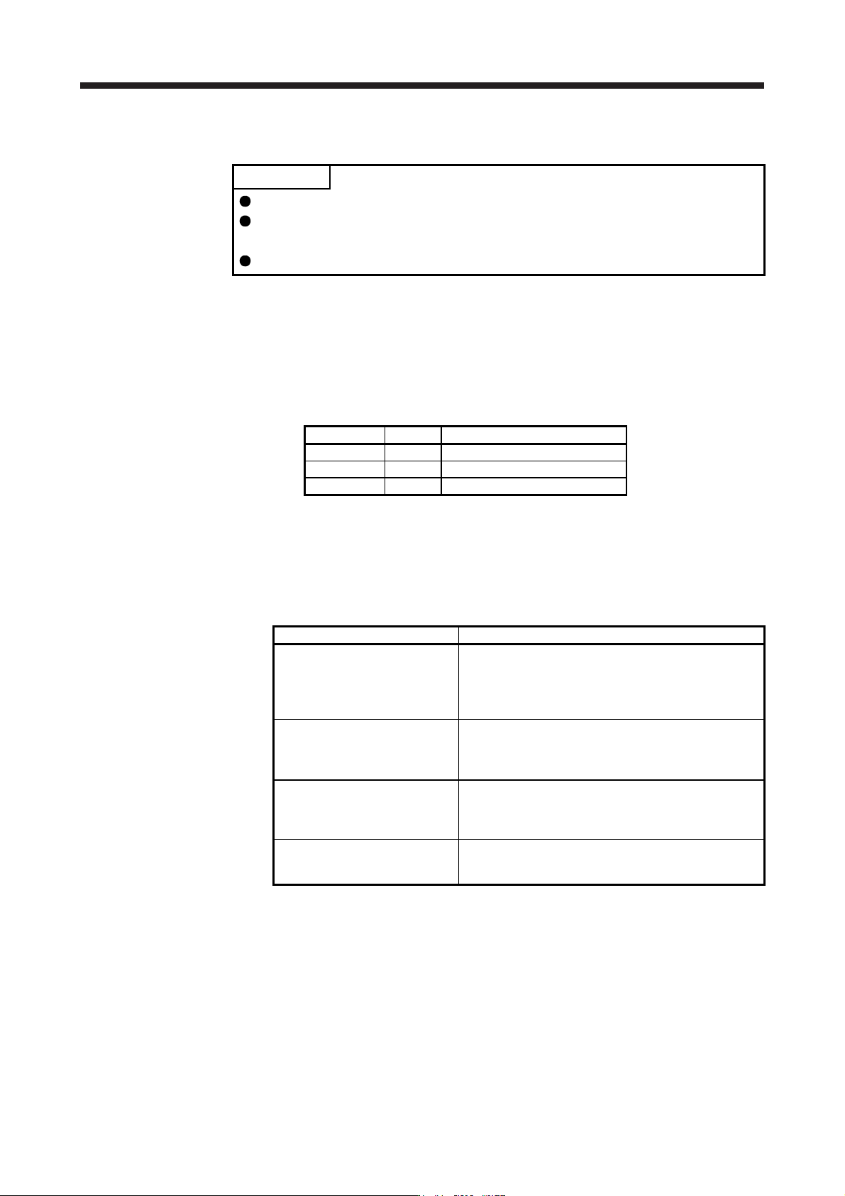
(3) Restrictions
The following functions are not available at model adaptive control disabled.
Function Explanation
Forced stop deceleration function
([Pr. PA04])
Disabling the model adaptive control while the forced stop
deceleration function is enabled, [AL. 37] will occur.
The forced stop deceleration function is enabled at factory
setting. Set [Pr. PA04] to "0 _ _ _" (Forced stop
deceleration function disabled).
Vibration suppression control 1
([Pr. PB02]/[Pr. PB19]/[Pr. PB20])
Vibration suppression control 2
([Pr. PB02]/[Pr. PB52]/[Pr. PB53])
The vibration suppression control uses the model adaptive
control. Disabling the model adaptive control will also
disable the vibration suppression control.
Overshoot amount compensation
([Pr. PB12])
The overshoot amount compensation uses data used by
the model adaptive control. Disabling the model adaptive
control will also disable the overshoot amount
compensation.
Super trace control
([Pr. PA22])
The super trace control uses the model adaptive control.
Disabling the model adaptive control will also disable the
super trace control.