sh030106u.pdf - 第267页
7. SPEC IAL ADJUSTMEN T FUNCT IONS 7 - 38 (2) Adjustm ent procedure POINT In the super trace c ontrol, d roop puls es are near 0 d uring th e servo motor control. T hus, the n orma l INP (In-p osition) may al ways be tur…
7. SPECIAL ADJUSTMENT FUNCTIONS
7 - 37
7.7 Super trace control
(1) Summary
In the normal position control, droop pulses are generated against the position control command from
the controller. Using the feed forward gain sets droop pulses at a constant speed to almost 0. However,
droop pulses generated during acceleration/deceleration cannot be suppressed.
With the ideal model in the servo amplifier, the super trace control enables to set constant speed and
uniform acceleration/deceleration droop pulses to almost 0 that cannot be coped with by the feed
forward gain.
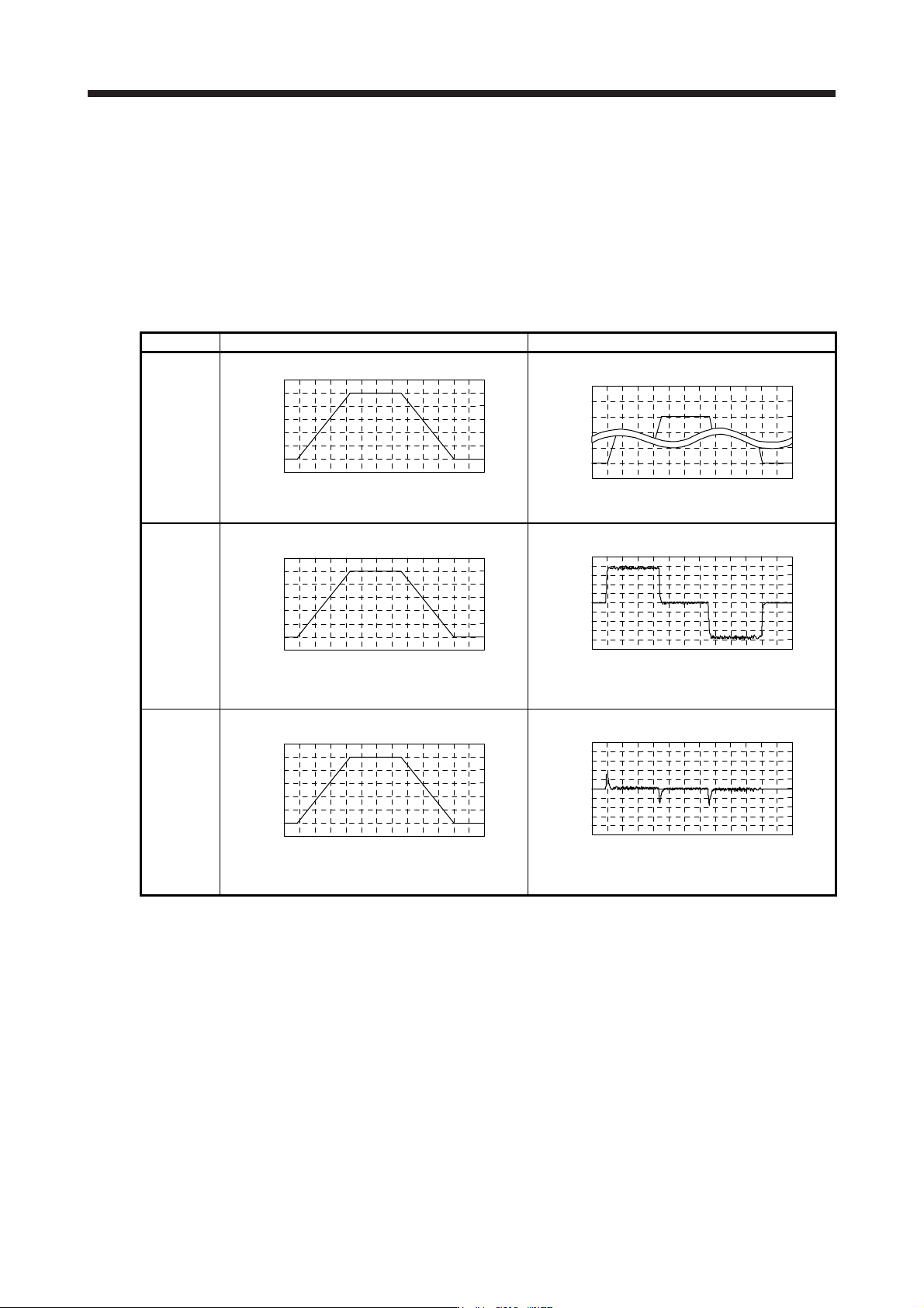
Control Position command (the same command) Droop pulses
Normal
control
Time
Servo motor speed
Time
Droop pulses
Droop pulses are always generated.
Feed
forward gain
Time
Servo motor speed
Time
Droop pulses
Droop pulses are generated during acceleration/
deceleration.
Super trace
control
Time
Servo motor speed
Time
Droop pulses
Droop pulses are almost 0 including the time of
acceleration or deceleration.
7. SPECIAL ADJUSTMENT FUNCTIONS
7 - 38
(2) Adjustment procedure
POINT
In the super trace control, droop pulses are near 0 during the servo motor
control. Thus, the normal INP (In-position) may always be turned on. Be sure to
set "INP (In-position) on condition selection" in [Pr. PD13] to " _ 1 _ _".
When you use the super trace control, it is recommended that the acceleration
time constant up to the rated speed be set to 1 s or more.
The following shows the adjustment procedure.
Step Operation
1
Execute the gain adjustment with one-touch tuning, auto tuning,
etc. Refer to chapter 6 for details.
2
Change the setting of auto tuning mode to the manual mode ([Pr.
PA08]: _ _ _ 3).
3
Change the setting of feed forward gain ([Pr. PB04]), and adjust
that droop pulses will be 0 at a constant speed.
4
Set the setting of INP (In-position) on condition selection ([Pr.
PD13]) to " _ 1 _ _".
5 Enable the super trace control. ([Pr. PA22]: _ _ 2 _)
6
Change the setting of model loop gain ([Pr. PB07]), and adjust
droop pulses during acceleration/deceleration.
8. TROUBLESHOOTING
8 - 1
8. TROUBLESHOOTING
POINT
Refer to "MELSERVO-J4 Servo Amplifier Instruction Manual (Troubleshooting)"
for details of alarms and warnings.
As soon as an alarm occurs, make the Servo-off status and interrupt the main
circuit power.
[AL. 37 Parameter error] and warnings (except [AL. F0 Tough drive warning]) are
not recorded in the alarm history.
When an error occurs during operation, the corresponding alarm and warning are displayed. When an alarm
or warning is displayed, refer to "MELSERVO-J4 Servo Amplifier Instruction Manual (Troubleshooting)" to
remove the failure. When an alarm occurs, ALM will turn off.
8.1 Explanation for the lists
(1) No./Name/Detail No./Detail name
Indicates each No./Name/Detail No./Detail name of alarms or warnings.
(2) Stop method
For the alarms and warnings in which "SD" is written in the stop method column, the servo motor stops
with the dynamic brake after forced stop deceleration. For the alarms and warnings in which "DB" or
"EDB" is written in the stop method column, the servo motor stops with the dynamic brake without forced
stop deceleration.
(3) Alarm deactivation
After the cause of the alarm has been removed, the alarm can be deactivated by any of the methods
marked
in the alarm deactivation column. Warnings are automatically canceled after the cause of
occurrence is removed. Alarms are deactivated with alarm reset, CPU reset, or cycling the power.
Alarm deactivation Explanation
Alarm reset 1. Reset command from controller
2. Clicking "Occurred Alarm Reset" in the "Alarm Display" window of MR
Configurator2
CPU reset Resetting the controller itself
Cycling the power Turning the power off and then turning it on again.