sh030106u.pdf - 第279页
8. TRO UBLESHO OTING 8 - 12 8.3 Warn ing lis t N o. Name Detail No. Detail name Stop meth od (Note 2, 3) Warning Home position return incom plete warning 90.1 Home posi tion ret urn i ncomplet e 90 90.2 Home position ret…
8. TROUBLESHOOTING
8 - 11
Note 1.
A
fter resolvin
g
the source of trouble, cool the equipment for approximatel
y
30 minutes.
2. The following shows three stop methods of DB, EDB, and SD.
DB: Stops with dynamic brake. (Coasts for the servo amplifier without dynamic brake.)
Coasts for MR-J4-03A6(-RJ) and MR-J4W2-0303B6. Note that EDB is applied when an alarm below occurs;
[AL. 30.1], [AL. 32.2], [AL. 32.4], [AL. 51.1], [AL. 51.2], [AL. 888]
EDB: Electronic dynamic brake stop (available with specified servo motors)
Refer to the following table for the specified servo motors. The stop method for other than the specified servo motors will
be DB.
Series Servo motor
HG-KR HG-KR053/HG-KR13/HG-KR23/HG-KR43
HG-MR HG-MR053/HG-MR13/HG-MR23/HG-MR43
HG-SR HG-SR51/HG-SR52
HG-AK HG-AK0136/HG-AK0236/HG-AK0336
SD: Forced stop deceleration
3. This is applicable when [Pr. PA04] is set to the initial value. The stop s
y
stem of SD can be chan
g
ed to DB usin
g
[Pr. PA04].
4. The alarm can be canceled by setting as follows:
For the fully closed loop control: set [Pr. PE03] to "1 _ _ _".
When a linear servo motor or direct drive motor is used: set [Pr. PL04] to "1 _ _ _".
5. In some controller communication status, the alarm factor ma
y
not be removed.
6. This alarm will occur onl
y
in the J3 compatibilit
y
mode.
7. Reset this while all the safet
y
observation functions are stopped.
8. TROUBLESHOOTING
8 - 12
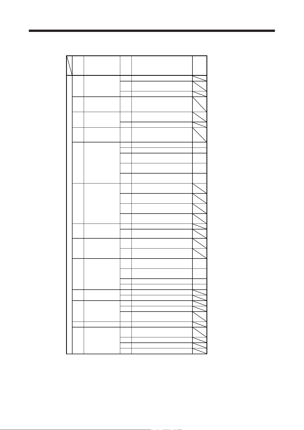
8.3 Warning list
No. Name
Detail
No.
Detail name
Stop
method
(Note 2,
3)
Warning
Home position
return incomplete
warning
90.1 Home position return incomplete
90 90.2
Home position return abnormal
termination
90.5 Z-phase unpassed
91
Servo amplifier
overheat warning
(Note 1)
91.1
Main circuit device overheat
warning
92
Battery cable
disconnection
warning
92.1
Encoder battery cable
disconnection warning
92.3 Battery degradation
93
ABS data transfer
warning
93.1
ABS data transfer requirement
warning during magnetic pole
detection
95.1 STO1 off detection DB
95.2 STO2 off detection DB
95 STO warning
95.3
STO warning 1 (safety observation
function)
DB
95.4
STO warning 2 (safety observation
function)
DB
95.5
STO warning 3 (safety observation
function)
DB
96.1
In-position warning at home
positioning
96
Home position
setting warning
96.2
Command input warning at home
positioning
96.3
Servo off warning at home
positioning
96.4
Home positioning warning during
magnetic pole detection
97
Positioning
specification
warning
97.1 Program operation disabled warning
97.2 Next station position warning
98
Software limit
warning
98.1
Forward rotation-side software
stroke limit reached
98.2
Reverse rotation-side software
stroke limit reached
99.1 Forward rotation stroke end off
(Note
4, 5)
99 Stroke limit warning
99.2 Reverse rotation stroke end off
(Note
4, 5)
99.4 Upper stroke limit off (Note 5)
99.5 Lower stroke limit off (Note 5)
9A
Optional unit input
data error warning
9A.1 Optional unit input data sign error
9A.2 Optional unit BCD input data error
9B
Error excessive
warning
9B.1 Excess droop pulse 1 warning
9B.3 Excess droop pulse 2 warning
9B.4
Error excessive warning during 0
torque limit
9C Converter error 9C.1 Converter unit error
9D.1
Station number switch change
warning
9D
CC-Link IE warning
1
9D.2 Master station setting warning
9D.3 Overlapping station number warning
9D.4 Mismatched station number warning
8. TROUBLESHOOTING
8 - 13
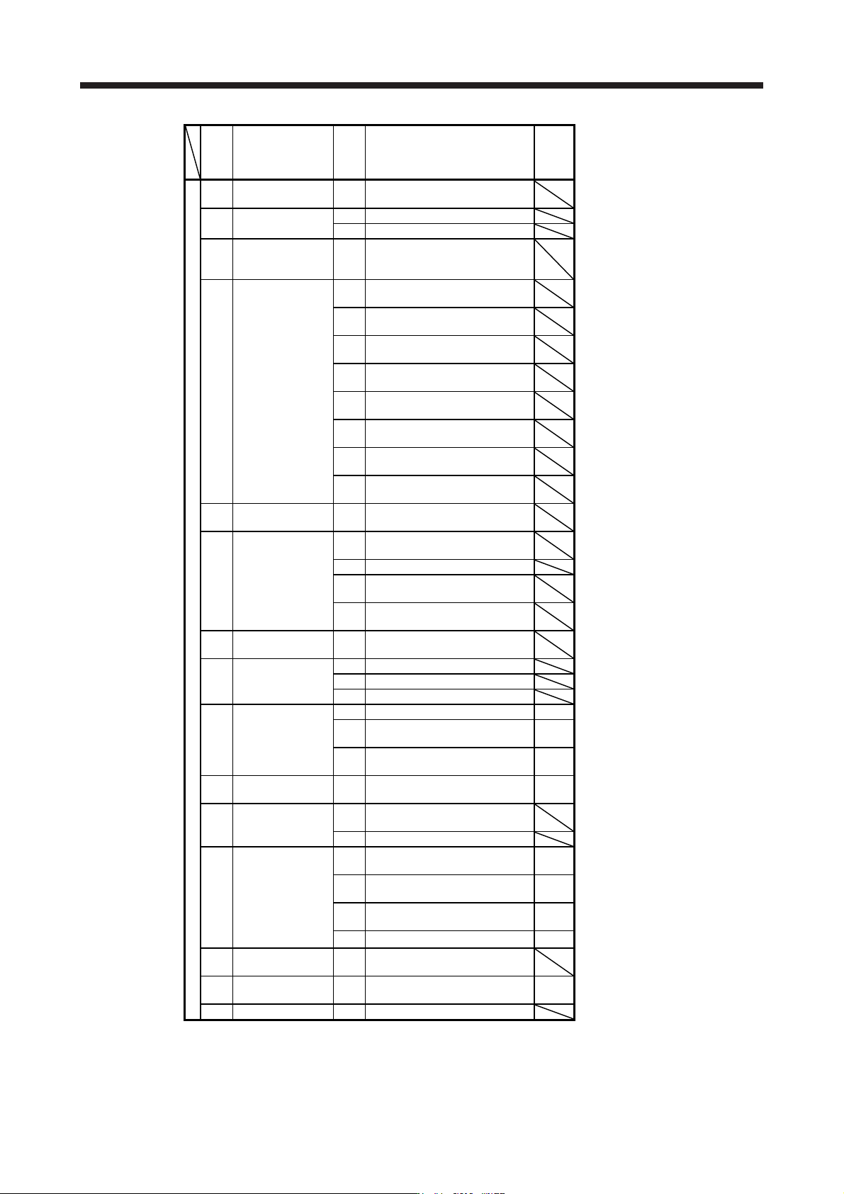
No. Name
Detail
No.
Detail name
Stop
method
(Note 2,
3)
Warning
9E
CC-Link IE warning
2
9E.1 CC-Link IE communication warning
9F Battery warning
9F.1 Low battery
9F.2 Battery degradation warning
E0
Excessive
regeneration
warning
E0.1 Excessive regeneration warning
E1.1
Thermal overload warning 1 during
operation
E1.2
Thermal overload warning 2 during
operation
E1.3
Thermal overload warning 3 during
operation
E1 Overload warning 1
E1.4
Thermal overload warning 4 during
operation
E1.5
Thermal overload error 1 during a
stop
E1.6
Thermal overload error 2 during a
stop
E1.7
Thermal overload error 3 during a
stop
E1.8
Thermal overload error 4 during a
stop
E2
Servo motor
overheat warning
E2.1 Servo motor temperature warning
E3.1
Multi-revolution counter travel
distance excess warning
E3
Absolute position
counter warning
E3.2 Absolute position counter warning
E3.4
Absolute positioning counter EEP-
ROM writing frequency warning
E3.5
Encoder absolute positioning
counter warning
E4 Parameter warning E4.1
Parameter setting range error
warning
E5
ABS time-out
warning
E5.1 Time-out during ABS data transfer
E5.2 ABSM off during ABS data transfer
E5.3 SON off during ABS data transfer
E6
Servo forced stop
warning
E6.1 Forced stop warning SD
E6.2
SS1 forced stop warning 1 (safety
observation function)
SD
E6.3
SS1 forced stop warning 2 (safety
observation function)
SD
E7
Controller forced stop
warning
E7.1 Controller forced stop warning SD
E8
Cooling fan speed
reduction warning
E8.1
Decreased cooling fan speed
warning
E8.2 Cooling fan stop
E9
Main circuit off
warning
E9.1
Servo-on signal on during main
circuit off
DB
E9.2
Bus voltage drop during low speed
operation
DB
E9.3
Ready-on signal on during main
circuit off
DB
E9.4 Converter unit forced stop DB
EA
ABS servo-on
warning
EA.1 ABS servo-on warning
EB
The other axis error
warning
EB.1 The other axis error warning DB
EC Overload warning 2 EC.1 Overload warning 2