sh030106u.pdf - 第281页
8. TRO UBLESHO OTING 8 - 14 N o. Name Detail No. Detail name Stop meth od (Note 2, 3) Warning ED Output w att excess warning ED.1 Output watt exc ess war ning F0 Tough drive w arni ng F0.1 Instantane ous p ower fail ure …
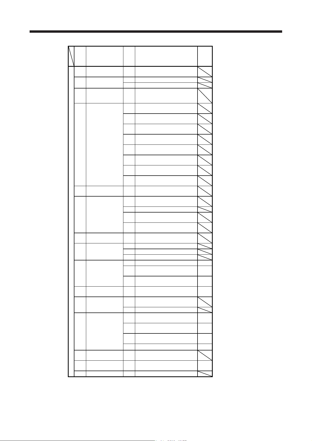
8. TROUBLESHOOTING
8 - 13
No. Name
Detail
No.
Detail name
Stop
method
(Note 2,
3)
Warning
9E
CC-Link IE warning
2
9E.1 CC-Link IE communication warning
9F Battery warning
9F.1 Low battery
9F.2 Battery degradation warning
E0
Excessive
regeneration
warning
E0.1 Excessive regeneration warning
E1.1
Thermal overload warning 1 during
operation
E1.2
Thermal overload warning 2 during
operation
E1.3
Thermal overload warning 3 during
operation
E1 Overload warning 1
E1.4
Thermal overload warning 4 during
operation
E1.5
Thermal overload error 1 during a
stop
E1.6
Thermal overload error 2 during a
stop
E1.7
Thermal overload error 3 during a
stop
E1.8
Thermal overload error 4 during a
stop
E2
Servo motor
overheat warning
E2.1 Servo motor temperature warning
E3.1
Multi-revolution counter travel
distance excess warning
E3
Absolute position
counter warning
E3.2 Absolute position counter warning
E3.4
Absolute positioning counter EEP-
ROM writing frequency warning
E3.5
Encoder absolute positioning
counter warning
E4 Parameter warning E4.1
Parameter setting range error
warning
E5
ABS time-out
warning
E5.1 Time-out during ABS data transfer
E5.2 ABSM off during ABS data transfer
E5.3 SON off during ABS data transfer
E6
Servo forced stop
warning
E6.1 Forced stop warning SD
E6.2
SS1 forced stop warning 1 (safety
observation function)
SD
E6.3
SS1 forced stop warning 2 (safety
observation function)
SD
E7
Controller forced stop
warning
E7.1 Controller forced stop warning SD
E8
Cooling fan speed
reduction warning
E8.1
Decreased cooling fan speed
warning
E8.2 Cooling fan stop
E9
Main circuit off
warning
E9.1
Servo-on signal on during main
circuit off
DB
E9.2
Bus voltage drop during low speed
operation
DB
E9.3
Ready-on signal on during main
circuit off
DB
E9.4 Converter unit forced stop DB
EA
ABS servo-on
warning
EA.1 ABS servo-on warning
EB
The other axis error
warning
EB.1 The other axis error warning DB
EC Overload warning 2 EC.1 Overload warning 2
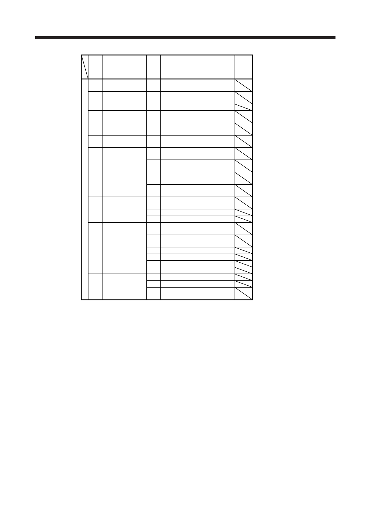
8. TROUBLESHOOTING
8 - 14
No. Name
Detail
No.
Detail name
Stop
method
(Note 2,
3)
Warning
ED
Output watt excess
warning
ED.1 Output watt excess warning
F0 Tough drive warning
F0.1
Instantaneous power failure tough
drive warning
F0.3 Vibration tough drive warning
F2
Drive recorder -
Miswriting warning
F2.1
Drive recorder - Area writing time-
out warning
F2.2
Drive recorder - Data miswriting
warning
F3
Oscillation detection
warning
F3.1 Oscillation detection warning
F4 Positioning warning
F4.4
Target position setting range error
warning
F4.6
Acceleration time constant setting
range error warning
F4.7
Deceleration time constant setting
range error warning
F4.9
Home position return type error
warning
F5
Simple cam
function - Cam data
miswriting warning
F5.1
Cam data - Area writing time-out
warning
F5.2 Cam data - Area miswriting warning
F5.3 Cam data checksum error
F6
Simple cam
function - Cam
control warning
F6.1
Cam axis one cycle current value
restoration failed
F6.2
Cam axis feed current value
restoration failed
F6.3 Cam unregistered error
F6.4 Cam control data setting range error
F6.5 Cam No. external error
F6.6 Cam control inactive
F7
Machine diagnosis
warning
F7.1 Vibration failure prediction warning
F7.2 Friction failure prediction warning
F7.3
Total travel distance failure
prediction warning
Note 1.
A
fter resolvin
g
the source of trouble, cool the equipment for approximatel
y
30 minutes.
2. The following shows two stop methods of DB and SD.
DB: Stops with dynamic brake. (Coasts for the servo amplifier without dynamic brake.)
Coasts for MR-J4-03A6(-RJ) and MR-J4W2-0303B6.
SD: Forced stop deceleration
3. This is applicable when [Pr. PA04] is set to the initial value. The stop system of SD can be changed to DB
usin
g
[Pr. PA04].
4. For MR-J4-
_
A_ servo amplifier, quick stop or slow stop can be selected usin
g
[Pr. PD30].
5. For MR-J4-_GF_ servo amplifier, quick stop or slow stop can be selected using [Pr. PD12]. (I/O mode
and CC-Link IE Field Network Basic
)
8. TROUBLESHOOTING
8 - 15
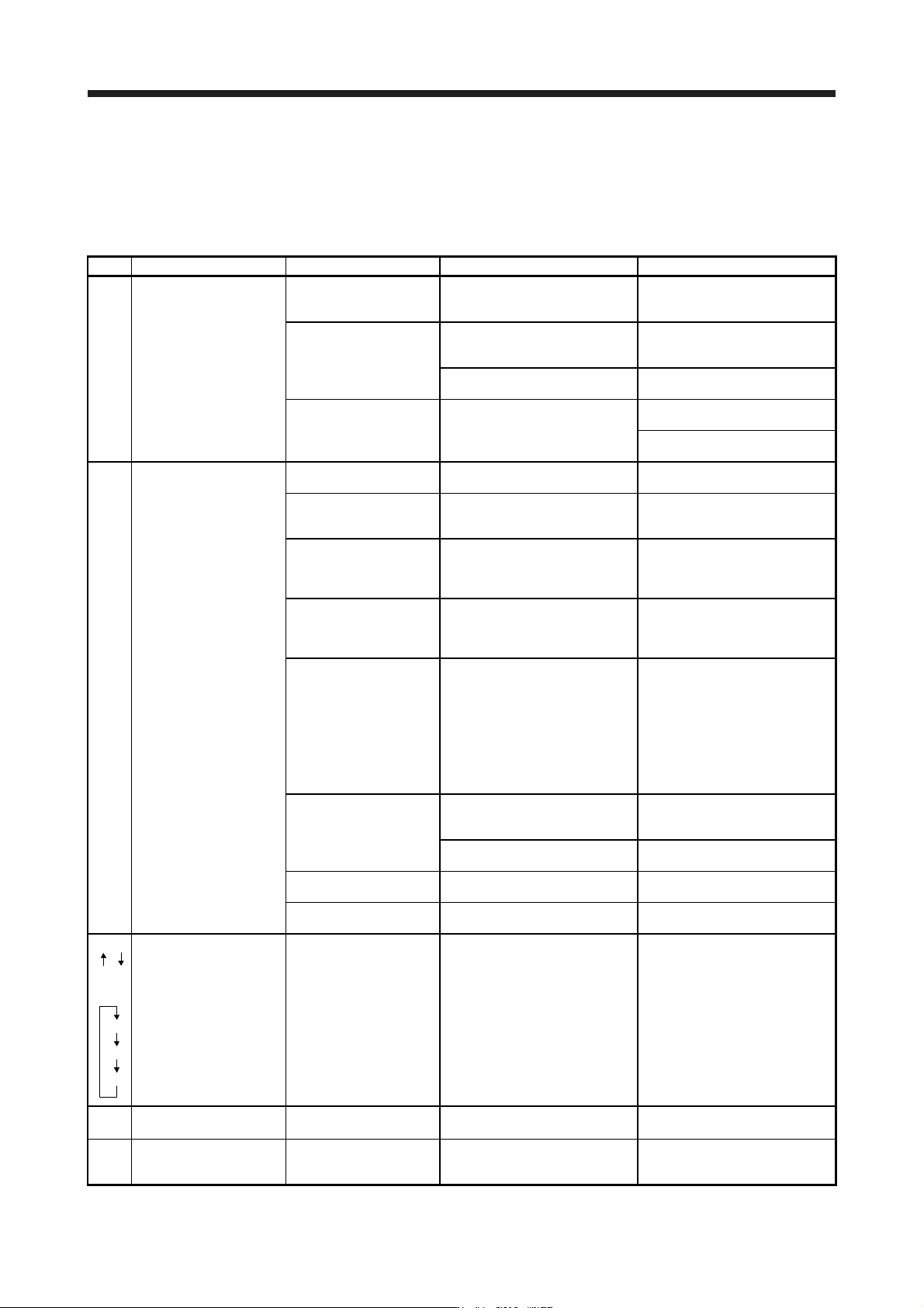
8.4 Troubleshooting at power on
When the servo system does not boot and system error occurs at power on of the servo system controller,
improper boot of the servo amplifier might be the cause. Check the display of the servo amplifier, and take
actions according to this section.
Display Description Cause Checkpoint Action
AA Communication with the
servo system controller
has disconnected.
The power of the servo
system controller was
turned off.
Check the power of the servo
system controller.
Switch on the power of the servo
system controller.
A SSCNET III cable was
disconnected.
"AA" is displayed in the
corresponding axis and following
axes.
Replace the SSCNET III cable of
the corresponding axis.
Check if the connectors (CNIA,
CNIB) are unplugged.
Connect it correctly.
The power of the servo
amplifier was turned off.
"AA" is displayed in the
corresponding axis and following
axes.
Check the power of the servo
amplifier.
Replace the servo amplifier of the
corresponding axis.
Ab Initialization
communication with the
servo system controller
has not completed.
The control axis is
disabled.
Check if the disabling control axis
switch (SW2-2) is on.
Turn off the disabling control axis
switch (SW2-2).
The setting of the axis
No. is incorrect.
Check that the other servo
amplifier is not assigned to the
same axis No.
Set it correctly.
Axis No. does not match
with the axis No. set to
the servo system
controller.
Check the setting and axis No. of
the servo system controller.
Set it correctly.
Information about the
servo series has not set
in the simple motion
module.
Check the value set in Servo
series (Pr 100) in the simple
motion module.
Set it correctly.
Communication cycle
does not match.
Check the communication cycle
at the servo system controller
side.
When using 8 axes or less: 0.222
ms
When using 16 axes or less:
0.444 ms
When using 32 axes or less:
0.888 ms
Set it correctly.
A SSCNET III cable was
disconnected.
"Ab" is displayed in the
corresponding axis and following
axes.
Replace the SSCNET III cable of
the corresponding axis.
Check if the connectors (CNIA,
CNIB) are unplugged.
Connect it correctly.
The power of the servo
amplifier was turned off.
"Ab" is displayed in an axis and
the following axes.
Check the power of the servo
amplifier.
The servo amplifier is
malfunctioning.
"Ab" is displayed in an axis and
the following axes.
Replace the servo amplifier of the
corresponding axis.
Ab
AC
or
Ab
AC
Ad
Communication between
servo system controller
and servo amplifier are
repeating connection and
shut-off.
An MR-J4-_B_(-RJ) servo
amplifier or MR-J4W_-_B
servo amplifier which is
set to J3 compatibility
mode is connected to the
SSCNET III/H network.
Check if the servo amplifier mode
is set to "J3 compatibility mode"
using "MR-J4(W)-B mode
selection" or "MR Mode Change"
included in MR Configurator2.
Use "MR-J4(W)-B mode
selection" or "MR Mode Change"
to switch the servo amplifier
mode to "J4 mode".
b##.
(Note)
The system has been in
the test operation mode.
Test operation mode has
been enabled.
Test operation setting switch
(SW2-1) is turned on.
Turn off the test operation setting
switch (SW2-1).
off Operation mode for
manufacturer setting is
set.
Operation mode for
manufacturer setting is
enabled.
Check if all of the control axis
setting switches (SW2) are on.
Set the control axis setting
switches (SW2) correctly.
Note. ## indicates axis No.