sh030106u.pdf - 第309页
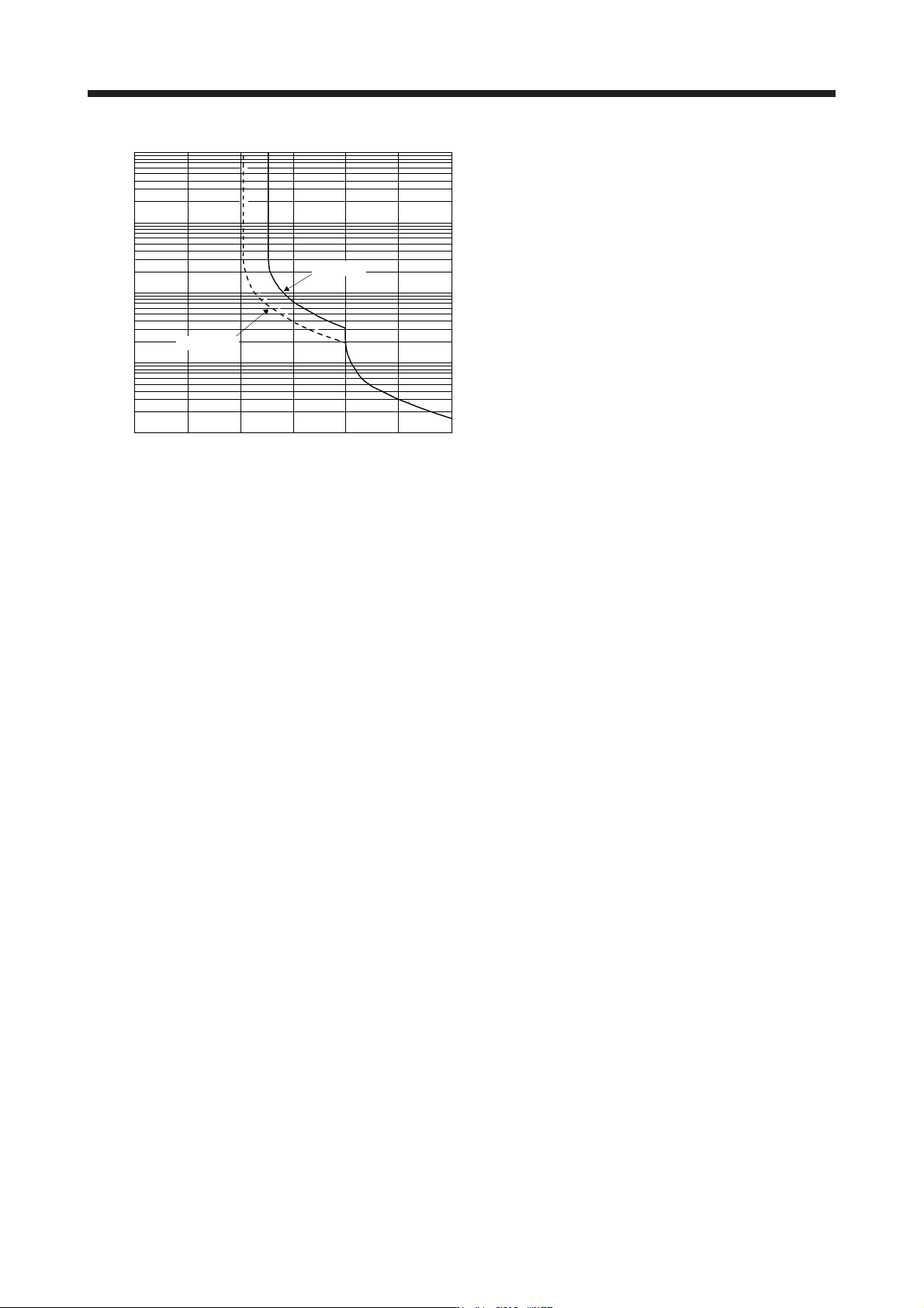
10. CHA RACT ERISTI CS 10 - 4 10000 1000 100 10 1 0 100 200 300 Operating Servo-lock 50 150 250 (Note 1) Load ratio [%] Operation time [s] Characterist ics e Note 1. If operation that generates torque more t han 100% of …
10. CHARACTERISTICS
10 - 3
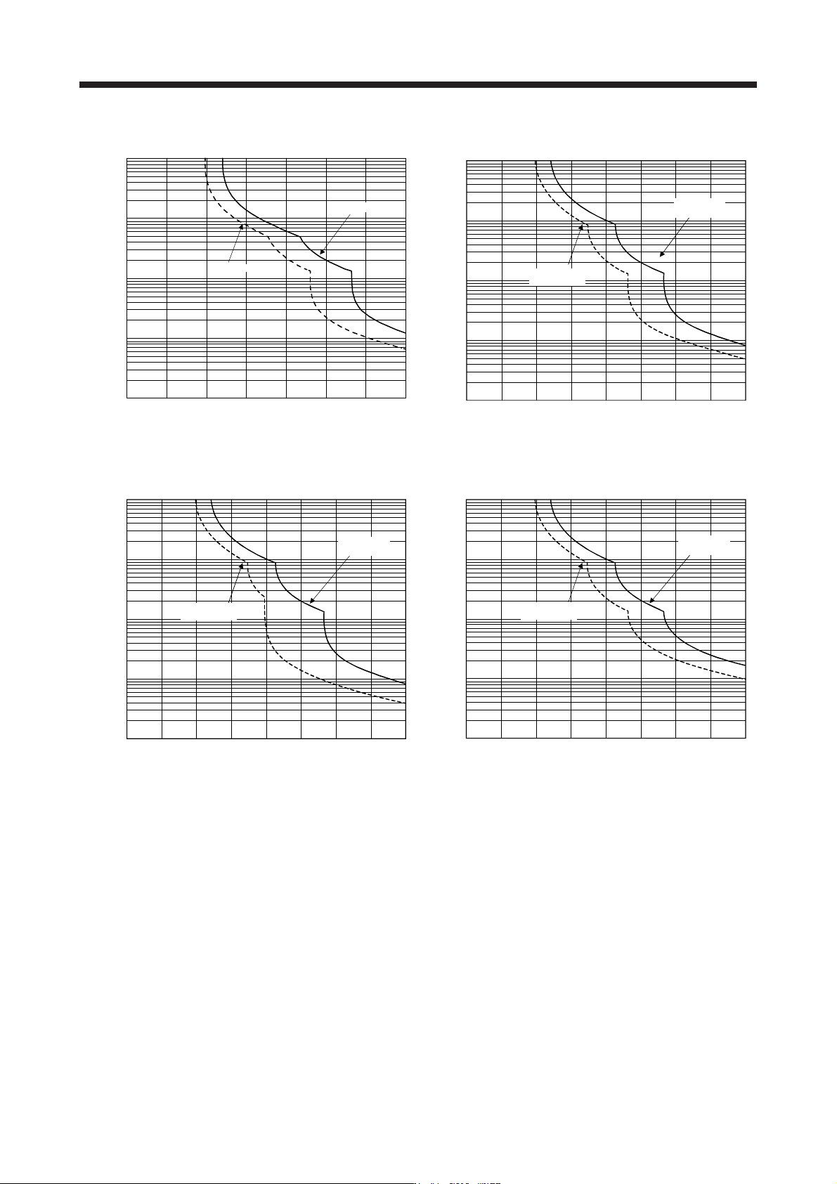
The following graphs show overload protection characteristics.
(Note 1, 2) Load ratio [%]
1000
100
10
1
0.1
100 200 300 350
0
50 150 250
Operating
Servo-lock
Operation time [s]
Characteristics a
1000
100
10
1
0.1
100 200 300 400
0 50 150 250 350
Load ratio [%]
(Note 1, 2, 3)
Servo-lock
Operating
Operation time [s]
Characteristics b
Load ratio [%]
(Note 1, 3)
1000
100
10
1
0.1
100 200 300 400
0
Servo-lock
Operating
Operation time [s]
50 150 250 350
Characteristics c
1000
100
10
1
0.1
100 200 300 400
0 50 150 250 350
Load ratio [%]
(Note 1, 3)
Servo-lock
Operating
Operation time [s]
Characteristics d
10. CHARACTERISTICS
10 - 4
10000
1000
100
10
1
0 100 200 300
Operating
Servo-lock
50 150 250
(Note 1) Load ratio [%]
Operation time [s]
Characteristics e
Note 1. If operation that generates torque more than 100% of the rating is performed with an abnormally high frequency in a servo
motor stop status (servo-lock status) or in a 50 r/min or less low-speed operation status, the servo amplifier may malfunction
re
g
ardless of the electronic thermal protection.
2. The load ratio ran
g
in
g
from 300% to 350% applies to the HG-KR servo motor.
3. The operation time at the load ratio of 300% to 400% applies when the maximum torque of HG-JR servo motor is increased to
400% of rated torque.
Fig. 10.1 Electronic thermal protection characteristics
10. CHARACTERISTICS
10 - 5
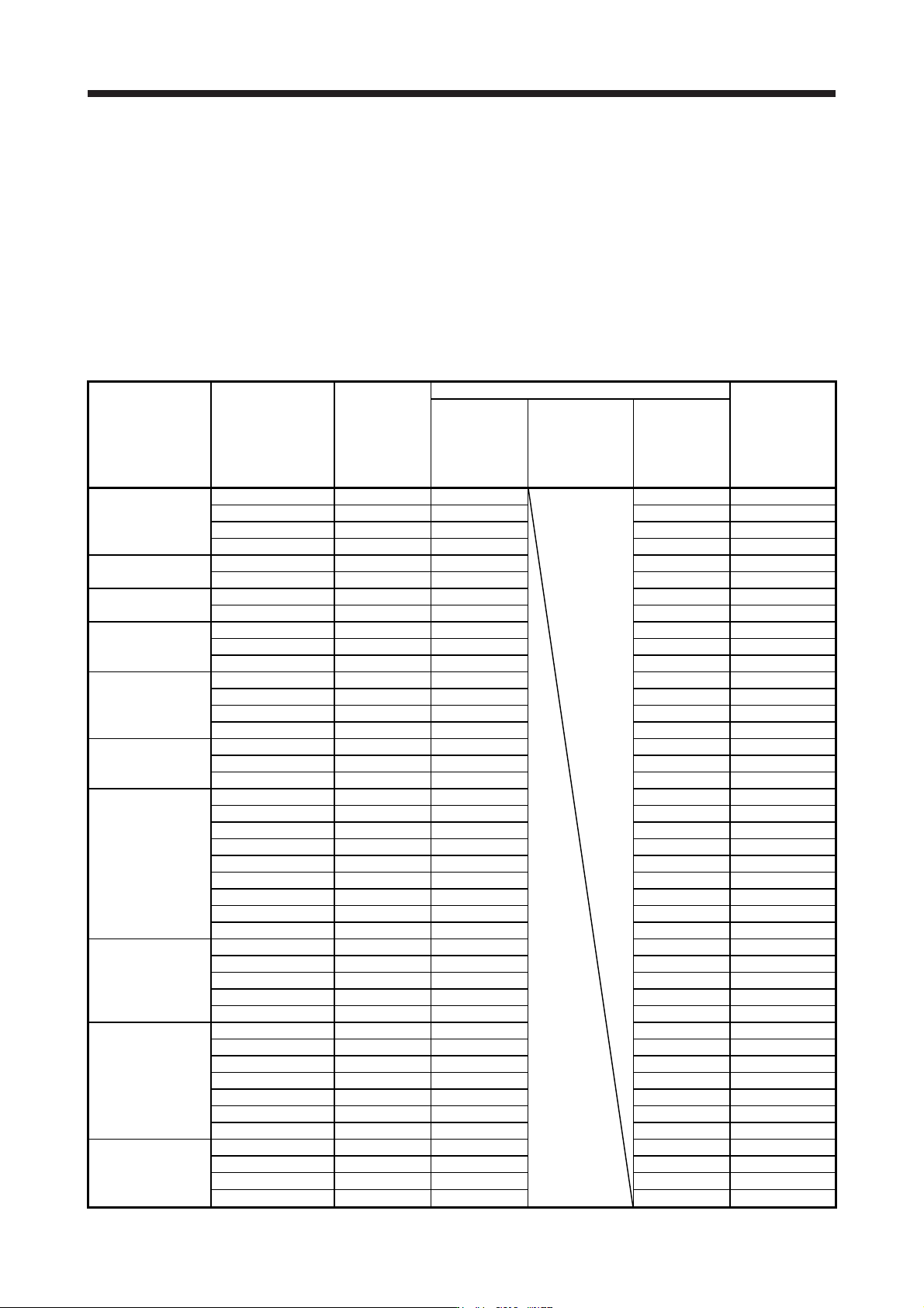
10.2 Power supply capacity and generated loss
(1) Amount of heat generated by the servo amplifier
Table 10.1 indicates servo amplifiers' power supply capacities and losses generated under rated load.
For thermal design of an enclosed type cabinet, use the values in the tables in consideration for the
harshest conditions with regard to the environment and operation pattern. The actual amount of
generated heat will be intermediate between values at rated torque and servo-off according to the duty
used during operation. When the servo motor is run at less than the rated speed, the power supply
capacity will be smaller than the value in the table, but the servo amplifier's generated heat will not
change.
Table 10.1 Power supply capacity and generated loss per servo motor
Servo amplifier Servo motor
Power supply
capacity
[kVA]
(Note 1)
Servo amplifier-generated heat [W] (Note 2)
Area required for
heat dissipation
[m
2
]
At rated output
At rated output
[Generated heat
in the cabinet
when cooled
outside the
cabinet] (Note 3)
With servo-off
MR-J4-10B(-RJ)
HG-MR053 0.3 25 15 0.5
HG-MR13 0.3 25 15 0.5
HG-KR053 0.3 25 15 0.5
HG-KR13 0.3 25 15 0.5
MR-J4-20B(-RJ)
HG-MR23 0.5 25 15 0.5
HG-KR23 0.5 25 15 0.5
MR-J4-40B(-RJ)
HG-MR43 0.9 35 15 0.7
HG-KR43 0.9 35 15 0.7
MR-J4-60B(-RJ)
HG-SR52 1.0 40 15 0.8
HG-SR51 1.0 40 15 0.8
HG-JR53 1.0 40 15 0.8
MR-J4-70B(-RJ)
HG-MR73 1.3 50 15 1.0
HG-KR73 1.3 50 15 1.0
HG-UR72 1.3 50 15 1.0
HG-JR73 1.3 50 15 1.0
MR-J4-100B(-RJ)
HG-SR102 1.7 50 15 1.0
HG-SR81 1.5 50 15 1.0
HG-JR103 1.7 50 15 1.0
MR-J4-200B(-RJ)
HG-SR152 2.5 90 20 1.8
HG-SR202 3.5 90 20 1.8
HG-SR121 2.1 90 20 1.8
HG-SR201 3.5 90 20 1.8
HG-RR103 1.7 50 15 1.0
HG-RR153 2.5 90 20 1.8
HG-UR152 2.5 90 20 1.8
HG-JR153 2.5 90 20 1.8
HG-JR203 3.5 90 20 1.8
MR-J4-350B(-RJ)
HG-SR352 5.5 130 20 2.6
HG-SR301 4.8 120 20 2.4
HG-RR203 3.5 90 20 1.8
HG-UR202 3.5 90 20 1.8
HG-JR353 5.5 160 20 2.7
MR-J4-500B(-RJ)
HG-SR502 7.5 195 25 3.9
HG-SR421 6.3 160 25 3.2
HG-RR353 5.5 135 25 2.7
HG-RR503 7.5 195 25 3.9
HG-UR352 5.5 195 25 3.9
HG-UR502 7.5 195 25 3.9
HG-JR503 7.5 195 25 3.9
MR-J4-700B(-RJ)
HG-SR702 10 300 25 6.0
HG-JR703 10 300 25 6.0
HG-JR701M 10 300 25 6.0
HG-JR601 8.6 250 25 5.0