sh030106u.pdf - 第314页
10. CHA RACT ERISTI CS 10 - 9 10.3.1 Dyna mic br ake op eration (1) Calculat ion of c oasting dist ance Fig. 10.3 sh ows the pa ttern in which the serv o mot or comes to a sto p when the dy nam ic brake is operated. Us e…
10. CHARACTERISTICS
10 - 8
10.3 Dynamic brake characteristics
CAUTION
The coasting distance is a theoretically calculated value that does not consider
factors such as friction. The calculated value will be longer than the actual
distance. If the braking distance is not longer than the calculated value, a moving
part may crash into the stroke end, causing a dangerous situation. Install an anti-
crash mechanism such as an air brake or an electric/mechanical stopper such as
a shock absorber to reduce the shock of moving parts.
POINT
Do not use dynamic brake to stop in a normal operation as it is the function to
stop in emergency.
For a machine operating at the recommended load to motor inertia ratio or less,
the estimated number of usage times of the dynamic brake is 1000 times while
the machine decelerates from the rated speed to a stop once in 10 minutes.
Be sure to enable EM1 (Forced stop 1) after servo motor stops when using EM1
(Forced stop 1) frequently in other than emergency.
Servo motors for MR-J4 may have the different coasting distance from that of
the previous model.
The electronic dynamic brake operates in the initial state for the HG series servo
motors of 600 W or smaller capacity. The time constant "τ" for the electronic
dynamic brake will be shorter than that of normal dynamic brake. Therefore,
coasting distance will be shorter than that of normal dynamic brake. For how to
set the electronic dynamic brake, refer to [Pr. PF06] and [Pr. PF12].
10. CHARACTERISTICS
10 - 9
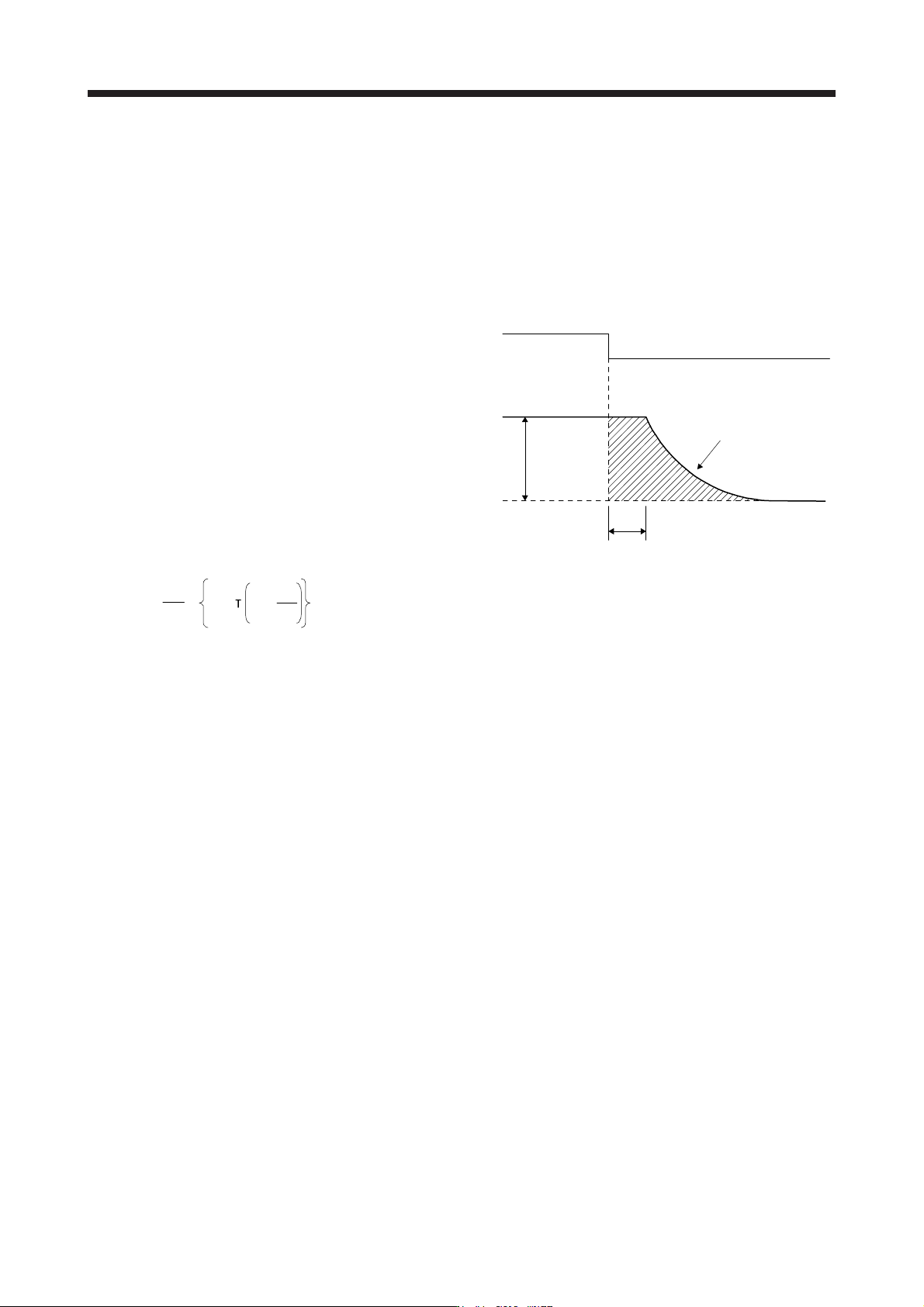
10.3.1 Dynamic brake operation
(1) Calculation of coasting distance
Fig. 10.3 shows the pattern in which the servo motor comes to a stop when the dynamic brake is
operated. Use equation 10.2 to calculate an approximate coasting distance to a stop. The dynamic brake
time constant τ varies with the servo motor and machine operation speeds. (Refer to (2) (a), (b) in this
section.)
A working part generally has a friction force. Therefore, actual coasting distance will be shorter than a
maximum coasting distance calculated with the following equation.
V
0
OFF
ON
Machine speed
t
e
Time
EM1 (Forced stop 1)
Dynamic brake
time constant τ
Fig. 10.3 Dynamic brake operation diagram
L
max
=
60
V
0
•
t
e
+
J
M
1 +
J
L
··························································································· (10.2)
L
max
: Maximum coasting distance ······················································································ [mm]
V
0
: Machine's fast feed speed ····················································································· [mm/min]
J
M
: Moment of inertia of the servo motor ··································································· [× 10
-4
kg•m
2
]
J
L
: Load moment of inertia converted into equivalent value on servo motor shaft ·············· [× 10
-4
kg•m
2
]
τ: Dynamic brake time constant ···························································································· [s]
t
e
: Delay time of control section ···························································································· [s]
For the servo amplifier of 7 kW or less, there is internal relay delay time of about 10 ms. For the servo
amplifier of 11 kW to 22 kW, there is delay caused by magnetic contactor built into the external
dynamic brake (about 50 ms) and delay caused by the external relay.
10. CHARACTERISTICS
10 - 10
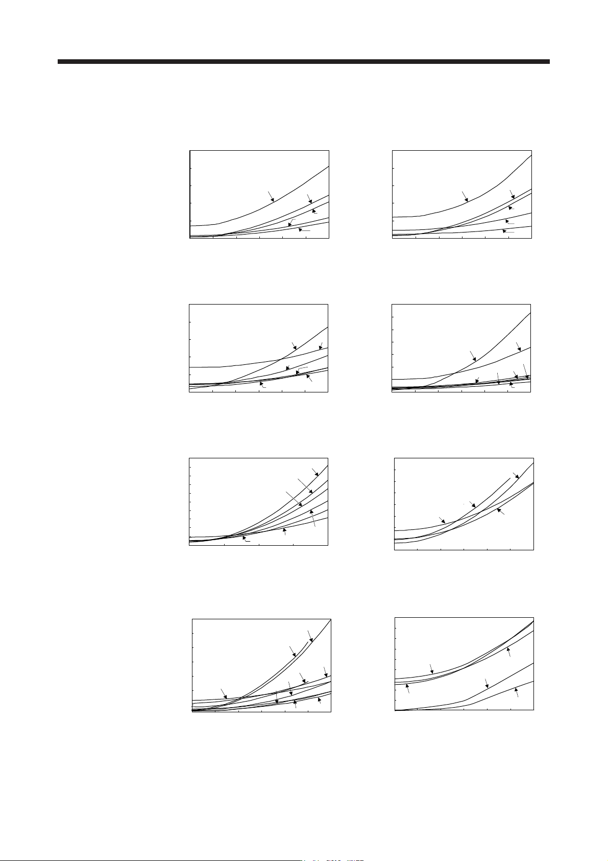
(2) Dynamic brake time constant
The following shows necessary dynamic brake time constant τ for equation 10.2.
(a) 200 V class
0
10
20
30
40
50
0 1000 2000 3000 4000 5000 6000
73
43
23
13
053
Speed [r/min]
Dynamic brake time
constant τ [ms]
Dynamic brake time
constant τ [ms]
0
10
20
30
40
50
0 1000 2000 3000 4000 5000 6000
73
43
23
13
053
Speed [r/min]
HG-MR series HG-KR series
121
0
20
40
60
80
100
0 250 500 750 1000 1250 1500
51 81
201
301
421
Dynamic brake time
constant τ [ms]
Speed [r/min]
0 500 1000 1500 2000 2500 3000
52
102
0
100
50
200
150
250
300
350
352
202
702
152
502
Dynamic brake time
constant τ [ms]
Speed [r/min]
HG-SR 1000 r/min series HG-SR 2000 r/min series
0
20
10
30
40
50
60
70
80
90
100
0 500 1000 1500 2000
15K1
25K1
20K1
801
60112K1
Speed [r/min]
Dynamic brake time
constant τ [ms]
Speed [r/min]
80
0
70
60
50
40
30
20
10
500 1000 1500 2000 2500 30000
15K1M
11K1M
22K1M
701M
Dynamic brake time
constant τ [ms]
HG-JR1000 r/min series HG-JR1500 r/min series
503
353
203
53
103
73
153
260
0
220
180
140
100
60
20
1000 2000 3000 4000 5000 60000
703
903
Servo motor speed [r/min]
Dynamic brake time
constant
τ
[ms]
0
2
4
6
8
10
12
14
16
18
0 500 1000 1500 2000 2500 3000
153
503103
353
203
Servo motor speed [r/min]
Dynamic brake time
constant
τ
[ms]
HG-JR3000 r/min series HG-RR series