sh030106u.pdf - 第319页
10. CHA RACT ERISTI CS 10 - 14 10.5 Inrus h currents at pow er-on of main circ uit and c ontrol c i rcuit POINT For a servo ampl ifier of 600 W or less , the inrush c urrent valu es c an chang e depending on fre quency o…
10. CHARACTERISTICS
10 - 13
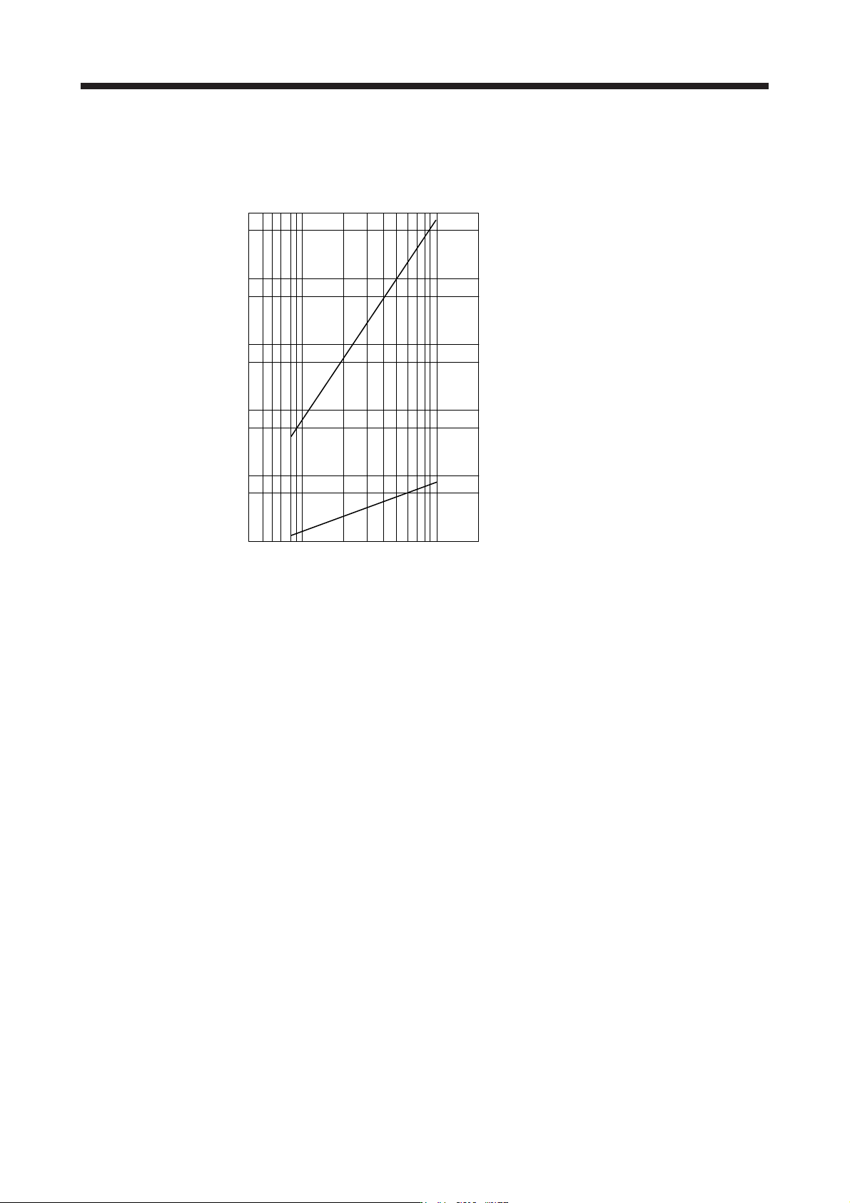
10.4 Cable bending life
The bending life of the cables is shown below. This graph calculated values. Since they are not guaranteed
values, provide a little allowance for these values.
a: Long bending life encoder cable
Long bending life motor power cable
Long bending life electromagnetic brake cable
SSCNET III cable using long distance cable
b: Standard encoder cable
Standard motor power cable
Standard electromagnetic brake cable
SSCNET III cable using inside panel standard cord
SSCNET III cable using outside panel standard cable
Number of bending times [time]
1 × 10
8
5 × 10
7
1 × 10
7
5 × 10
6
1 × 10
6
5 × 10
5
1 × 10
5
5 × 10
4
1 × 10
4
5 × 10
3
1 × 10
3
Bend radius [mm]
4 7 10 20 40 70 100 200
b
a
10. CHARACTERISTICS
10 - 14
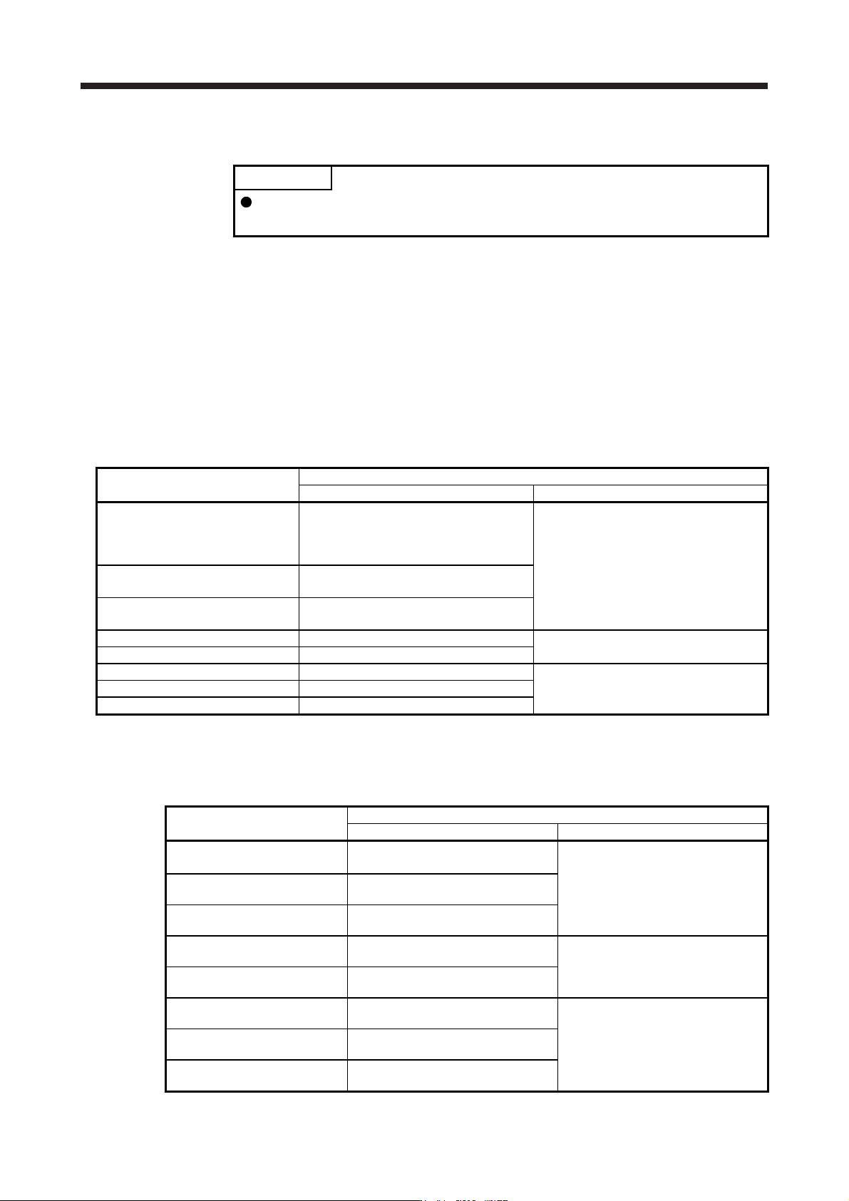
10.5 Inrush currents at power-on of main circuit and control circuit
POINT
For a servo amplifier of 600 W or less, the inrush current values can change
depending on frequency of turning on/off the power and ambient temperature.
A molded-case circuit breaker and magnetic contactor may fail or malfunction due to an inrush current
flowing through the servo amplifier's power lines (input lines) at power on. Therefore, use products with the
specifications as described. (Refer to section 11.10.)
When circuit protectors are used, it is recommended that the inertia delay type, which is not tripped by an
inrush current, be used.
(1) 200 V class
The following shows the inrush currents (reference data) that will flow when 240 V AC servo amplifier) is
applied at the power supply capacity. Even when you use a 1-phase 200 V AC power supply with MR-
J4-10B(-RJ) to MR-J4-200B(-RJ), the inrush currents of the main circuit power supply is the same.
Servo amplifier
Inrush currents (A
0-P
)
Main circuit power supply (L1/L2/L3) Control circuit power supply (L11/L21)
MR-J4-10B(-RJ)
MR-J4-20B(-RJ)
MR-J4-40B(-RJ)
MR-J4-60B(-RJ)
30 A (attenuated to approx. 3 A in 20 ms)
20 A to 30 A
(attenuated to approx. 1 A in 20 ms)
MR-J4-70B(-RJ)
MR-J4-100B(-RJ)
34 A (attenuated to approx. 7 A in 20 ms)
MR-J4-200B(-RJ)
MR-J4-350B(-RJ)
113 A (attenuated to approx. 12 A in 20 ms)
MR-J4-500B(-RJ) 42 A (attenuated to approx. 20 A in 20 ms)
34 A
(attenuated to approx. 2 A in 20 ms)
MR-J4-700B(-RJ) 85 A (attenuated to approx. 20 A in 30 ms)
MR-J4-11KB(-RJ) 226 A (attenuated to approx. 30 A in 30 ms)
42 A
(attenuated to approx. 2 A in 30 ms)
MR-J4-15KB(-RJ) 226 A (attenuated to approx. 50 A in 30 ms)
MR-J4-22KB(-RJ) 226 A (attenuated to approx. 70 A in 30 ms)
(2) 400 V class
The following shows the inrush currents (reference data) that will flow when 480 V AC is applied at the
power supply capacity.
Servo amplifier
Inrush currents (A
0-P
)
Main circuit power supply (L1/L2/L3) Control circuit power supply (L11/L21)
MR-J4-60B4(-RJ)
MR-J4-100B4(-RJ)
65 A
(attenuated to approx. 5 A in 10 ms)
40 A to 50 A
(attenuated to approx. 0 A in 2 ms)
MR-J4-200B4(-RJ)
80 A
(attenuated to approx. 5 A in 10 ms)
MR-J4-350B4(-RJ)
100 A
(attenuated to approx. 20 A in 10 ms)
MR-J4-500B4(-RJ)
65 A
(attenuated to approx. 9 A in 20 ms)
41 A
(attenuated to approx. 0 A in 3 ms)
MR-J4-700B4(-RJ)
68 A
(attenuated to approx. 34 A in 20 ms)
MR-J4-11KB4(-RJ)
339 A
(attenuated to approx. 10 A in 30 ms)
38 A
(attenuated to approx. 1 A in 30 ms)
MR-J4-15KB4(-RJ)
339 A
(attenuated to approx. 15 A in 30 ms)
MR-J4-22KB4(-RJ)
339 A
(attenuated to approx. 20 A in 30 ms)

10. CHARACTERISTICS
10 - 15
(3) 100 V class
The following shows the inrush currents (reference data) that will flow when 120 V AC is applied at the
power supply capacity.
Servo amplifier
Inrush currents (A
0-P
)
Main circuit power supply (L1/L2) Control circuit power supply (L11/L21)
MR-J4-10B1(-RJ)
MR-J4-20B1(-RJ)
MR-J4-40B1(-RJ)
38 A
(attenuated to approx. 14 A in 10 ms)
20 A to 30 A
(attenuated to approx. 0 A
in 1 ms to 2 ms)