sh030106u.pdf - 第322页
11. OPT ION S AND P ERI PHER AL EQU IPMENT 11 - 1 11. OPTIONS AND PERIPH ERAL EQUIPME NT WARNING Before c onnectin g any opt ion or p erip heral eq uipment, turn of f the po wer and w ait for 15 mi nutes or more unt il t…

10. CHARACTERISTICS
10 - 16
MEMO
11. OPTIONS AND PERIPHERAL EQUIPMENT
11 - 1
11. OPTIONS AND PERIPHERAL EQUIPMENT
WARNING
Before connecting any option or peripheral equipment, turn off the power and wait
for 15 minutes or more until the charge lamp turns off. Then, confirm that the
voltage between P+ and N- is safe with a voltage tester and others. Otherwise, an
electric shock may occur. In addition, when confirming whether the charge lamp is
off or not, always confirm it from the front of the servo amplifier.
CAUTION
Use the specified peripheral equipment and options to prevent a malfunction or a
fire.
POINT
We recommend using HIV wires to wire the servo amplifiers, options, and
peripheral equipment. Therefore, the recommended wire sizes may differ from
those used for the previous servo amplifiers.
11.1 Cable/connector sets
POINT
The IP rating indicated for cables and connectors is their protection against
ingress of dust and raindrops when they are connected to a servo amplifier or
servo motor. If the IP rating of the cable, connector, servo amplifier and servo
motor vary, the overall IP rating depends on the lowest IP rating of all
components.
Please purchase the cable and connector options indicated in this section.
11. OPTIONS AND PERIPHERAL EQUIPMENT
11 - 2
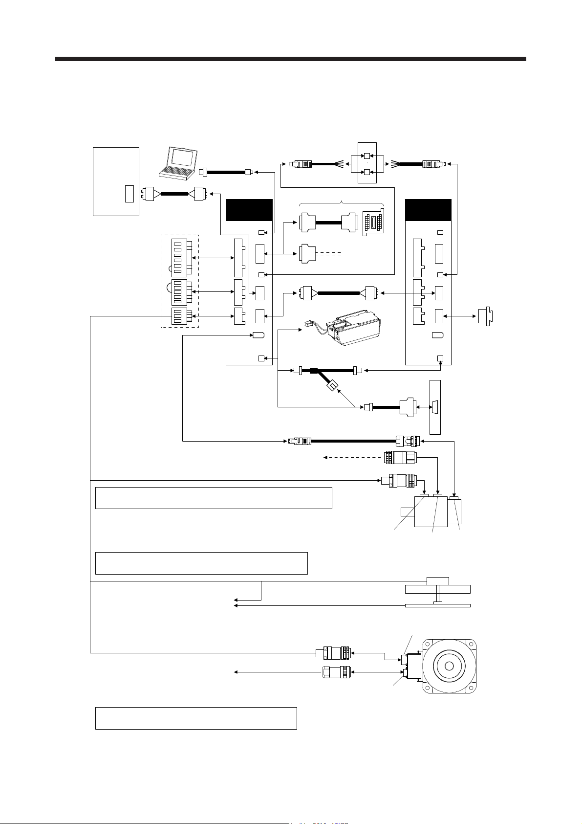
11.1.1 Combinations of cable/connector sets
For MR-J4-_B_ servo amplifier
Refer to "Servo Motor Instruction Manual (Vol. 3)" for options for
servo motor power supply, electromagnetic brake, and encoder.
6)
CN1A
CN1B
CN3
CNP1
CNP2
CNP3
CN1A
CN1B
CN2
CN3
7)
2) 3) 4)
5)
2) 3) 4)
CN2
CN8
CN5
CN8
CN5
CN4 CN4
Refer to "Linear Encoder Instruction Manual" about options
for linear encoder.
Refer to "Direct Drive Motor Instruction Manual" about
options for direct drive motor power and encoder.
8) 8)
CN9
CN10
Servo
amplifier
Cap
(packed with the
servo amplifier)
(Note 1)
Servo system
controller
Personal
computer
1) (packed with the servo amplifier)
Servo
amplifier
(Note 2)
To 24 V DC power supply
for electromagnetic brake
Servo motor
Encoder
connector
Brake
connector
Power
connector
Linear servo motor
Linear encoder
Power connector
Direct drive motor
Encoder connector
To CN2
To CN2
The connection method changes
depending on incremental system
and absolute position detection system.
Safety logic uni
t
MR-J3-D05
(Note 2)
Battery
11)
10)
Battery unit
MR-BT6VCASE and
MR-BAT6V1 battery
Note 1. Connectors for 3.5 kW or less. For 5 kW or more, it is a terminal block.
2. When not usin
g
the STO function, attach the short-circuit connector
(
9
))
came with a servo amplifier.