sh030106u.pdf - 第327页
11. OPT ION S AND P ERI PHER AL EQU IPMENT 11 - 6 11.1.2 MR-D 05UDL3M- B S TO cable This cabl e is for connec ting an exter nal devic e to t he CN8 c onn ector . Cable model Cable length Cable OD (Note) Applic ation MR-D…
11. OPTIONS AND PERIPHERAL EQUIPMENT
11 - 5
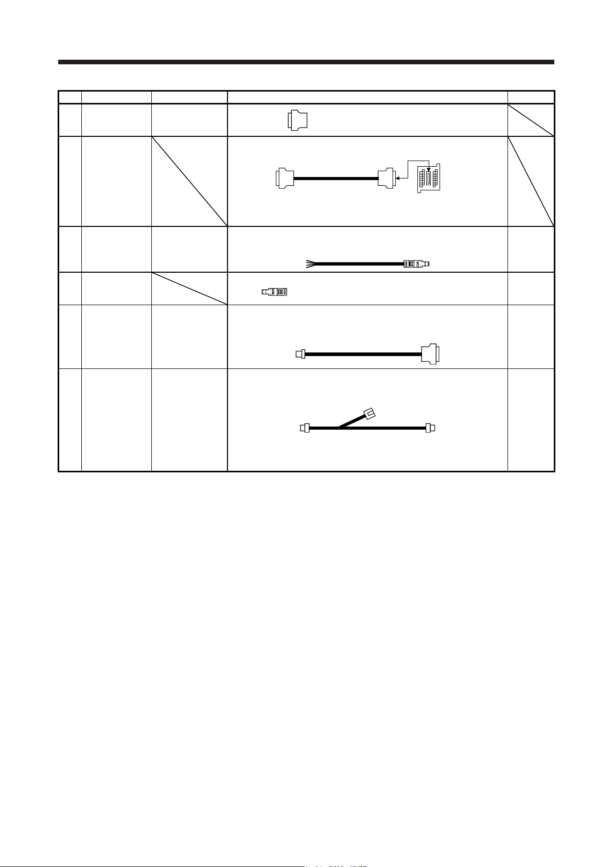
No. Product name Model Description Remark
6) Connector set MR-CCN1
Connector: 10120-3000PE
Shell kit: 10320-52F0-008
(3M or equivalent)
7)
Junction terminal
block
(recommended)
MR-J2HBUS_M
PS7DW-20V14B-F
(Toho Technology)
Junction terminal block PS7DW-20V14B-F is not option. For using the
junction terminal block, option MR-J2HBUS_M is necessary. Refer to
section 11.6 for details.
8) STO cable MR-D05UDL3M-B Connector set: 2069250-1
(TE Connectivity)
Connection
cable for
the CN8
connector
9)
Short-circuit
connector
Supplied
with servo
amplifier
10) Battery cable MR-BT6V1CBL_M
Cable length:
0.3/1 m
(Refer to section
11.1.4.)
Housing: PAP-02V-O
Contact: SPHD-001G-P0.5
(JST)
Connector: 10114-3000PE
Shell kit: 10314-52F0-008
(3M or equivalent)
For
connection
with battery
unit
11)
Junction battery
cable
MR-BT6V2CBL_M
Cable length:
0.3/1 m
(Refer to section
11.1.4.)
Housing: PAP-02V-O
Contact: SPHD-001G-P0.5
(JST)
Housing: PALR-02VF-O
Contact: SPAL-001GU-P0.5
(JST)
For battery
junction
Housing: PAP-02V-O
Contact: SPHD-001G-P0.5
(JST)
11. OPTIONS AND PERIPHERAL EQUIPMENT
11 - 6
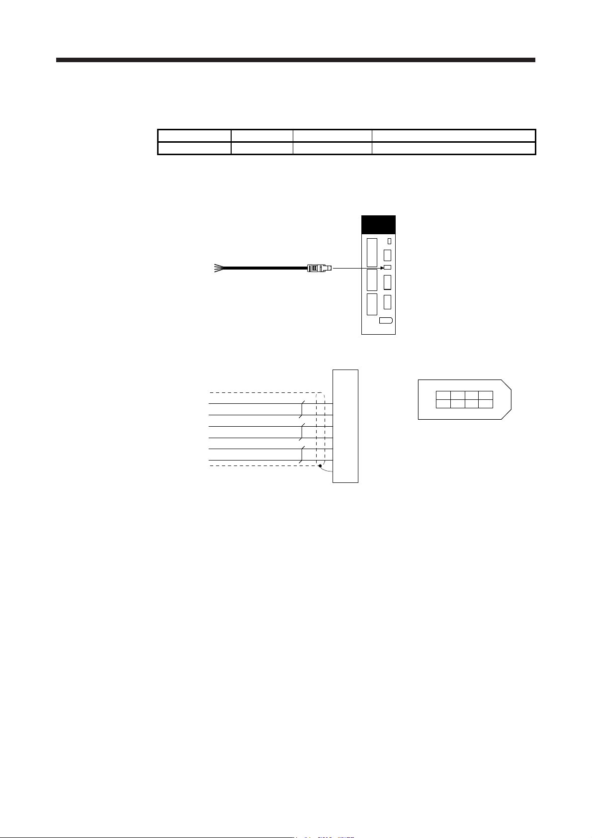
11.1.2 MR-D05UDL3M-B STO cable
This cable is for connecting an external device to the CN8 connector.
Cable model Cable length Cable OD (Note) Application
MR-D05UDL3M-B 3 m 5.7 mm Connection cable for the CN8 connector
Note. Standard OD. The maximum OD is about 10 %
g
reater for dimensions without tolerances.
(1) Configuration diagram
Servo amplifier
MR-D05UDL3M-B
CN8
(2) Internal wiring diagram
1
2
3
6
7
Plate
STO2
TOFB1
TOFB2
Shield
STO1
TOFCOM
8
4
5
STOCOM
Yellow (with black dots)
Yellow (with red dots)
Gray (with black dots)
Gray (with red dots)
White (with black dots)
White (with red dots)
(Note)
2
1
64 8
CN8 connector
357
Viewed from the connection part
Note. Do not use the two core wires with oran
g
e insulator
(
with red or black dots
)
.
11. OPTIONS AND PERIPHERAL EQUIPMENT
11 - 7
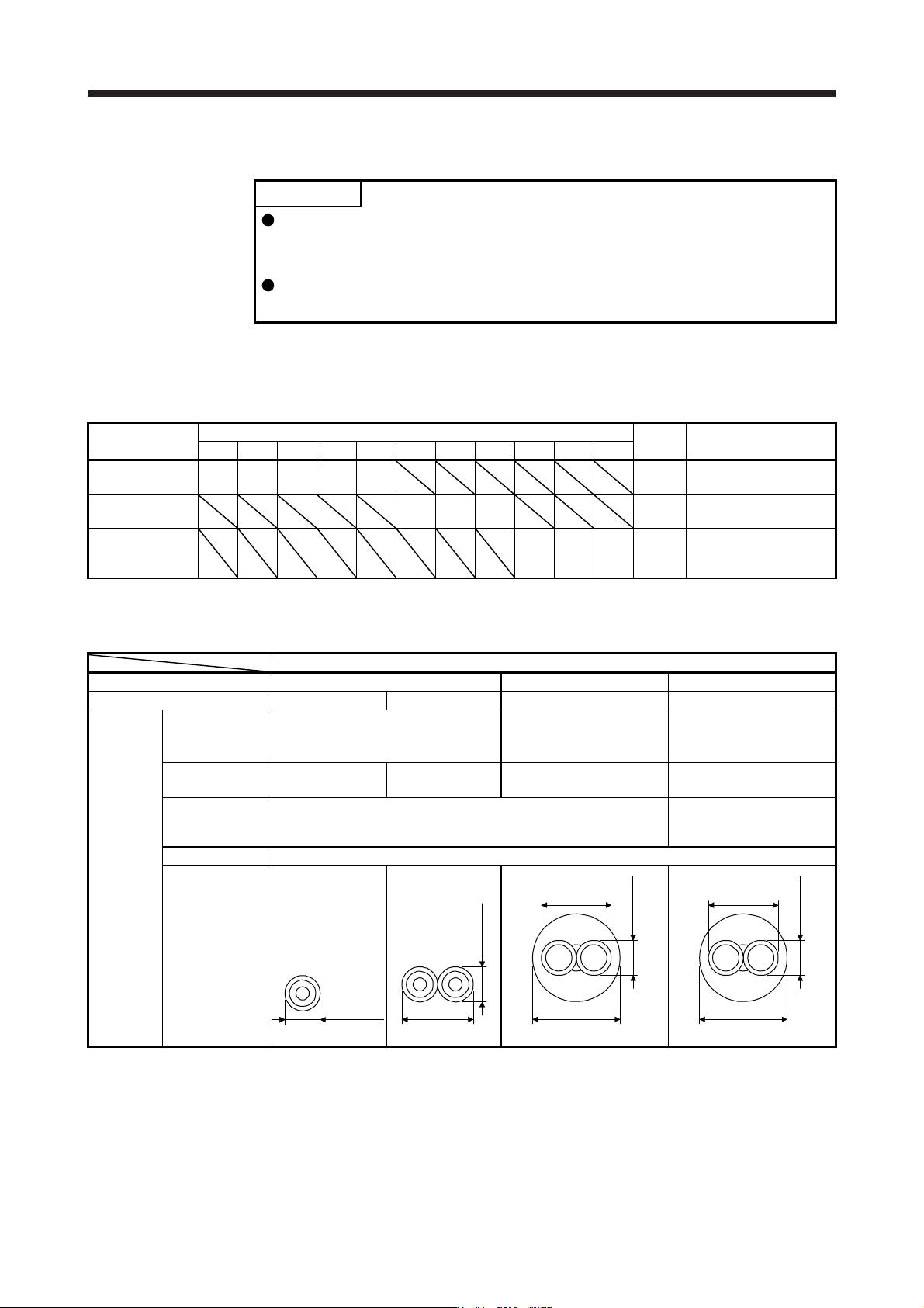
11.1.3 SSCNET III cable
POINT
Do not look directly at the light generated from CN1A/CN1B connector of servo
amplifier or the end of SSCNET III cable. The light can be a discomfort when it
enters the eye.
Refer to app. 10 for long distance cable over 50 m and ultra-long bending life
cable.
(1) Model explanations
The numbers in the cable length field of the table indicate the symbol filling the underline "_" in the cable
model. The cables of the lengths with the symbols are available.
Cable model
Cable length
Bending
life
Application/remark
0.15 m 0.3 m 0.5 m 1 m 3 m 5 m 10 m 20 m 30 m 40 m 50 m
MR-J3BUS_M 015 03 05 1 3 Standard
Using standard cord
inside cabinet
MR-J3BUS_M-A 5 10 20 Standard
Using standard cable
outside cabinet
(Note)
MR-J3BUS_M-B
304050
Long
bending
life
Using long distance
cable
Note. For cable of 30 m or shorter, contact
y
our local sales office.
(2) Specifications
Description
SSCNET III cable model MR-J3BUS_M MR-J3BUS_M-A MR-J3BUS_M-B
SSCNET III cable length 0.15 m 0.3 m to 3 m 5 m to 20 m 30 m to 50 m
Optical
cable
(cord)
Minimum bend
radius
25 mm
Enforced covering cable:
50 mm
Cord: 25 mm
Enforced covering cable:
50 mm
Cord: 30 mm
Tension strength 70 N 140 N
420 N
(Enforced covering cable)
980 N
(Enforced covering cable)
Temperature
range for use
(Note)
-40 °C to 85 °C -20 °C to 70 °C
Ambience Indoors (no direct sunlight), no solvent or oil
Appearance [mm]
2.2 ± 0.07
4.4 ± 0.1
2.2 ± 0.07
4.4 ± 0.1
6.0 ± 0.2
2.2 ± 0.07
4.4 ± 0.4
7.6 ± 0.5
2.2 ± 0.2
Note. This temperature range for use is the value for optical cable (cord) only. Temperature condition for the connector is the same as
that for servo amplifier.