sh030106u.pdf - 第333页
11. OPT ION S AND P ERI PHER AL EQU IPMENT 11 - 12 11.2.2 Sel ectio n of rege nerativ e opt ion A regener ative o ption f or a hor izontal axis c an be s ele cted wit h t he rou gh calc ulat ion shown in this sect ion. T…
11. OPTIONS AND PERIPHERAL EQUIPMENT
11 - 11
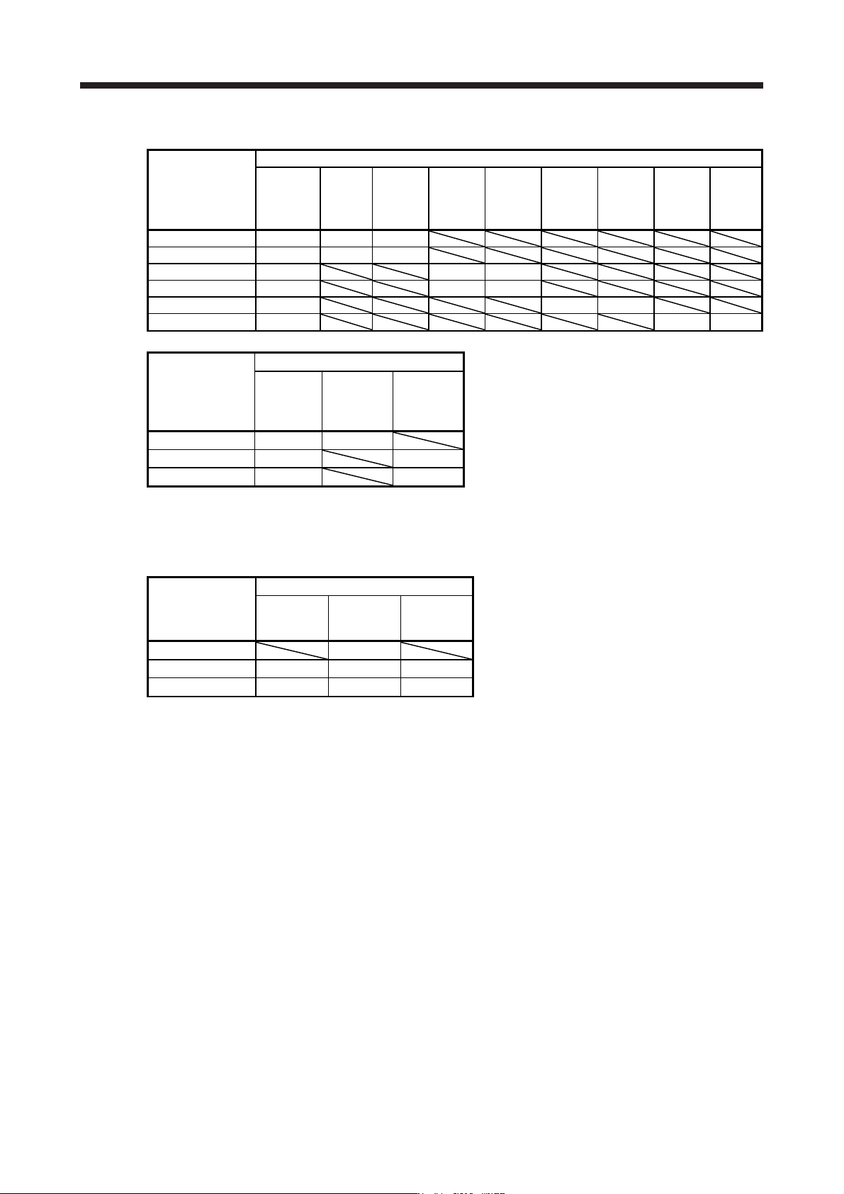
(2) 400 V class
Servo amplifier
Regenerative power [W]
Built-in
regenerative
resistor
MR-
RB1H-4
[82 Ω]
(Note 1)
MR-
RB3M-4
[120 Ω]
(Note 1)
MR-
RB3G-4
[47 Ω]
(Note 1)
MR-
RB5G-4
[47 Ω]
(Note 1)
MR-
RB34-4
[26 Ω]
(Note 1)
MR-
RB54-4
[26 Ω]
(Note 1)
MR-
RB3U-4
[22 Ω]
(Note 1)
MR-
RB5U-4
[22 Ω]
MR-J4-60B4(-RJ) 15 100 300
MR-J4-100B4(-RJ) 15 100 300
MR-J4-200B4(-RJ) 100 300 500
MR-J4-350B4(-RJ) 100 300 500
MR-J4-500B4(-RJ) 130 300 500
MR-J4-700B4(-RJ) 170 300 500
Servo amplifier
(Note 2) Regenerative power [W]
External
regenerative
resistor
(accessory)
MR-RB5K-4
[10 Ω]
MR-RB6K-4
[10 Ω]
MR-J4-11KB4(-RJ) 500 (800) 500 (800)
MR-J4-15KB4(-RJ) 850 (1300) 850 (1300)
MR-J4-22KB4(-RJ) 850 (1300) 850 (1300)
Note 1.
A
lwa
y
s install a coolin
g
fan.
2. Values in parentheses assume the installation of a coolin
g
fan.
(3) 100 V class
Servo amplifier
Regenerative power [W]
Built-in
regenerative
resistor
MR-RB032
[40 Ω]
MR-RB12
[40 Ω]
MR-J4-10B1(-RJ) 30
MR-J4-20B1(-RJ) 10 30 100
MR-J4-40B1(-RJ) 10 30 100
11. OPTIONS AND PERIPHERAL EQUIPMENT
11 - 12
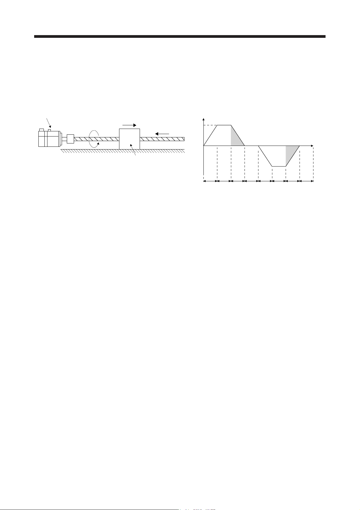
11.2.2 Selection of regenerative option
A regenerative option for a horizontal axis can be selected with the rough calculation shown in this section.
To select a regenerative option precisely, use the capacity selection software.
(1) Rotary servo motor
(a) Regenerative energy calculation
Servo motor
Moving part
N
V
W
L
F
C
2)
1)
V
3)
4)
Forward
rotation
6)
5) 7)
Reverse
rotation
8)
Time
Feed speed of moving part
t
psa1 t1 tpsd1 t2 tpsa2 t3 t4tpsd2
V: Feed speed of moving part [mm/min]
N: Servo motor speed (N = V/ΔS) [r/min]
Δ
S: Travel distance per servo motor
revolution (ΔS = P
B
)
[mm/rev]
P
B
: Ball screw lead [mm]
L
B
: Ball screw length [mm]
D
B
: Ball screw diameter [mm]
W
L
: Moving part mass [kg]
F
C
: Load antidrag setting [N]
T
L
: Load torque converted into equivalent
value on servo motor shaft [N•m]
[N•m]
η: Drive system efficiency
µ: Friction coefficient
J
L
: Load moment of inertia converted into
equivalent value on servo motor shaft
[kg•cm
2
]
J
M
: Moment of inertia of the servo motor [kg•cm
2
]
π: Pi constant
g: Gravitational acceleration [m/s
2
]

11. OPTIONS AND PERIPHERAL EQUIPMENT
11 - 13
Formulas for calculating torque and energy in operation
Regenerative
power
Torque applied to servo motor [N•m]
(Note 1, 2)
Energy E [J]
1)
T
1
=
9.55 • 10
4
(J
L
/η+ J
M
) • N
•
t
psa1
1
+ T
L
E
1
=
2
0.1047
• N • T
1
• t
psa1
2) T
2
= T
L
E
2
= 0.1047 • N • T
2
• t
1
3)
T
3
=
9.55 • 10
4
-(J
L
• η+ J
M
) • N
•
t
psd1
1
+ T
L
E
3
=
2
0.1047
• N • T
3
• t
psd1
4), 8) T
4
, T
8
= 0 E
4
, E
8
= 0 (No regeneration)
5)
T
5
=
9.55 • 10
4
(J
L
/η+ J
M
) • N
•
t
psa2
1
+ T
L
E
5
=
2
0.1047
• N • T
5
• t
psa2
6) T
6
= T
L
E
6
= 0.1047 • N • T
6
• t
3
7)
T
7
=
9.55 • 10
4
-(J
L
• η+ J
M
) • N
•
t
psd2
1
+ T
L
E
7
=
2
0.1047
• N • T
7
• t
psd2
Note 1. Load torque converted into equivalent value on servo motor shaft T
L
can be calculated
with the following expression.
T
L
=
{(
F
C
+
(
µ× W
L
×
g))
×
Δ
S
}
/
(
2000 × π × η
)
2. Load moment of inertia converted into equivalent value on servo motor shaft J
L
can be
calculated with the following expression.
J
L
= J
L1
+ J
L2
+ J
L3
J
L1
is the load moment of inertia of the moving part, J
L2
is the load moment of inertia of
the ball screw, and J
L3
is the load moment of inertia of the coupling. J
L1
and J
L2
can be
calculated with the following expressions.
J
L1
= W
L
× (ΔS/(20 × π))
2
J
L2
=
{(
π × 0.0078 ×
(
L
B
/
10
))
/32
}
×
(
D
B
/
10
)
4
From the calculation results in 1) to 8), find the absolute value (Es) of the sum total of negative
energies.