sh030106u.pdf - 第347页
11. OPT ION S AND P ERI PHER AL EQU IPMENT 11 - 26 (6) MR-RB1H-4 [Unit: mm] 156 168 144 6 2 149 173 6 Approx. 6 Approx. 24 6 15 φ 6 mounting hole 36 40 TE1 terminal P C G3 G4 Applic able wire size: AWG 24 to 10 Tightenin…
11. OPTIONS AND PERIPHERAL EQUIPMENT
11 - 25
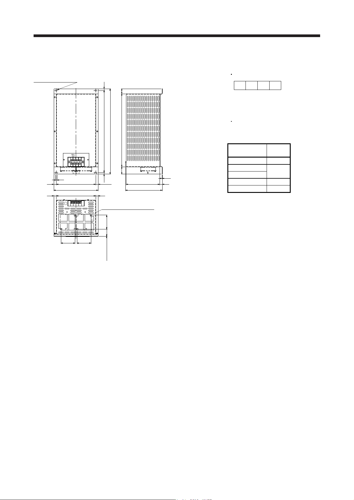
(5) MR-RB5R/MR-RB9F/MR-RB9T/MR-RB5K-4/MR-RB6K-4
[Unit: mm]
480
10
260
230
10
2-φ10 mounting hole
500
30427
43
197
15
2.3
Cooling fan intake
215
15
23015
10
15 15
82.5
82.582.5
Approx. 42
Cooling fan mounting
screw (4-M3 screw)
TE1 terminal block
PCG3G4
Terminal screw size: M5
Tightening torque: 2.0 [N•m]
Mounting screw
Screw size: M8
Tightening torque: 13.2 [N•m]
Regenerative
option
Mass
[kg]
MR-RB5R 10
MR-RB9F
11
MR-RB9T
MR-RB5K-4 10
MR-RB6K-4 11
11. OPTIONS AND PERIPHERAL EQUIPMENT
11 - 26
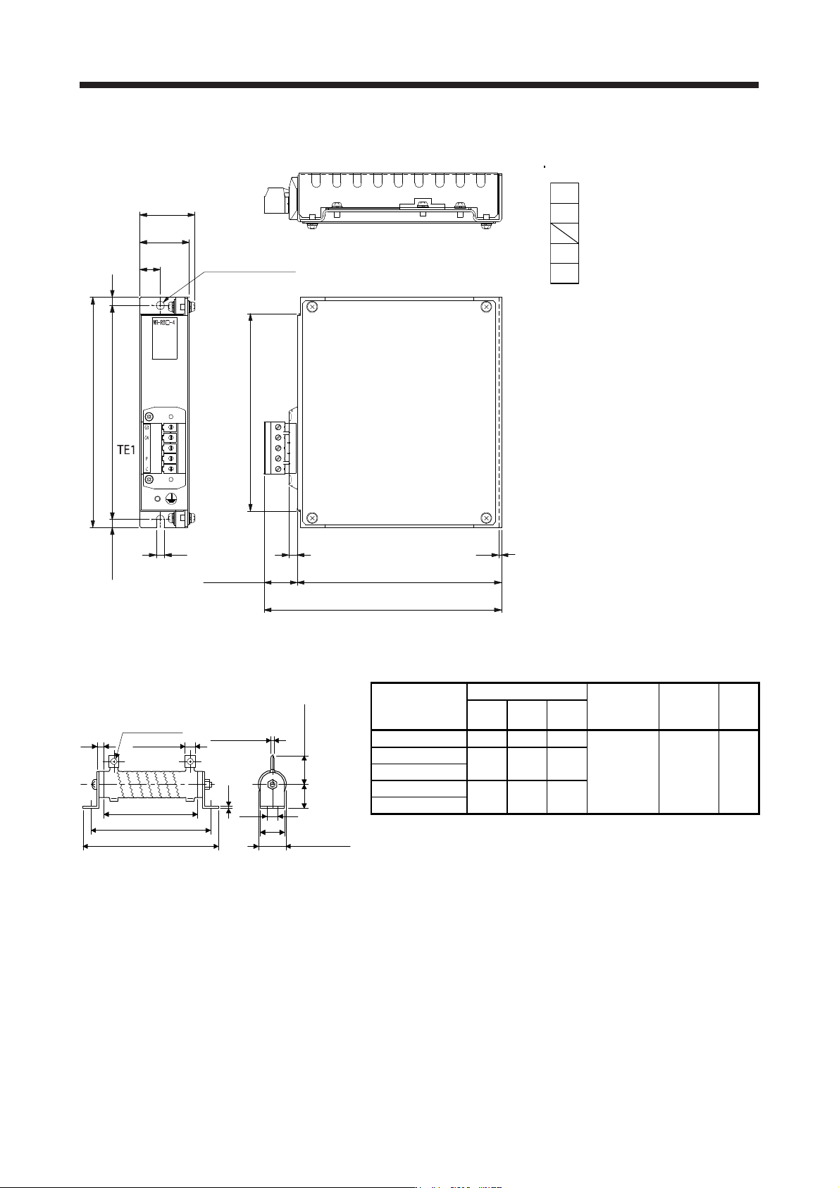
(6) MR-RB1H-4
[Unit: mm]
156
168
144
6
2
149
173
6
Approx. 6
Approx. 24
6
15
φ6 mounting hole
36
40
TE1 terminal
P
C
G3
G4
Applicable wire size: AWG 24 to 10
Tightening torque: 0.5 to 0.6 [N•m]
Mounting screw
Screw size: M5
Tightening torque: 3.24 [N•m]
Mass: 1.1 [kg]
(7) GRZG400-0.8Ω/GRZG400-0.6Ω/GRZG400-0.5Ω/GRZG400-2.5Ω/GRZG400-2.0Ω (standard
accessories)
[Unit: mm]
Approx. K
1.6
Approx. φ47
9.5
40
411
385
10
Approx. φC
Approx. A
Approx. 2.4
40
Approx. 330
Regenerative
resistor
Variable dimensions
Mounting
screw size
Tightening
torque
[N•m]
Mass
[kg]
A C K
GRZG400-0.8Ω 10 5.5 39
M8 13.2 0.8
GRZG400-0.6Ω
16 8.2 46
GRZG400-0.5Ω
GRZG400-2.5Ω
10 5.5 39
GRZG400-2.0Ω
11. OPTIONS AND PERIPHERAL EQUIPMENT
11 - 27
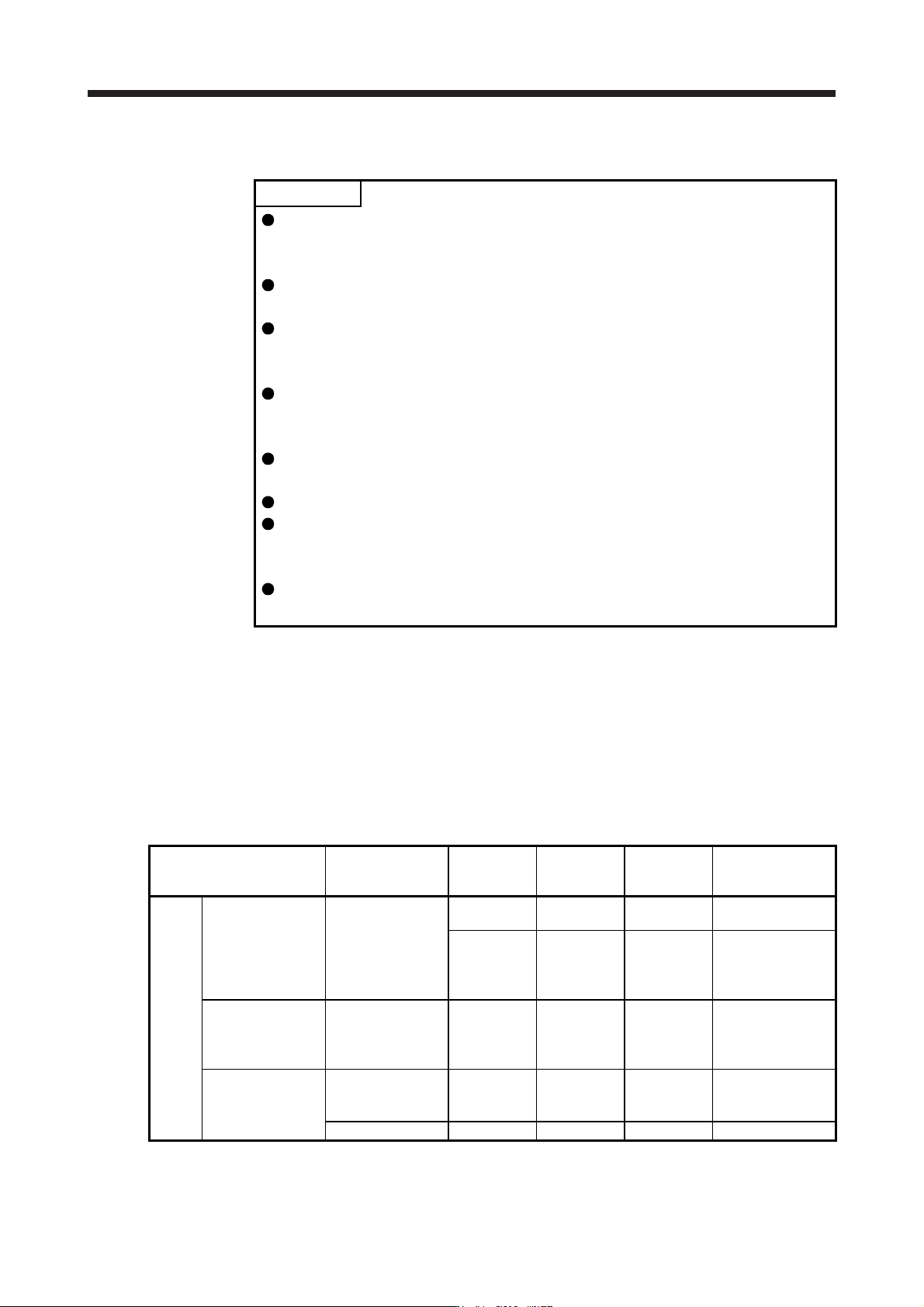
11.3 FR-BU2-(H) brake unit
POINT
Use a 200 V class brake unit and a resistor unit with a 200 V class servo
amplifier, and a 400 V class brake unit and a resistor unit with a 400 V class
servo amplifier. Combination of different voltage class units cannot be used.
When a brake unit and a resistor unit are installed horizontally or diagonally, the
heat dissipation effect diminishes. Install them on a flat surface vertically.
The temperature of the resistor unit case will be higher than the ambient
temperature by 100 ˚C or over. Keep cables and flammable materials away from
the case.
Ambient temperature condition of the brake unit is between -10 ˚C and 50 ˚C.
Note that the condition is different from the ambient temperature condition of the
servo amplifier (between 0 ˚C and 55 ˚C).
Configure the circuit to shut down the power-supply with the alarm output of the
brake unit and the resistor unit under abnormal condition.
Use the brake unit with a combination indicated in section 11.3.1.
To perform continuous regenerative operation, use the FR-RC-(H) power
regeneration converter, FR-CV-(H) power regeneration common converter, or
FR-XC-(H) multifunction regeneration converter.
Brake unit and regenerative options (Regenerative resistor) cannot be used
simultaneously.
Connect the brake unit to the bus of the servo amplifier. As compared to the MR-RB regenerative option, the
brake unit can return larger power. Use the brake unit when the regenerative option cannot provide sufficient
regenerative capability.
When using the brake unit, set [Pr. PA02] to "_ _ 0 1".
When using the brake unit, always refer to the FR-BU2 Instruction Manual.
11.3.1 Selection
Use a combination of servo amplifier, brake unit and resistor unit listed below.
Brake unit Resistor unit
Number of
connected
units
Permissible
continuous
power [kW]
Resultant
resistance [Ω]
Applicable servo
amplifier (Note 3)
200 V
class
FR-BU2-15K FR-BR-15K 1 0.99 8
MR-J4-500B(-RJ)
(Note 1)
2 (parallel) 1.98 4 MR-J4-500B(-RJ)
MR-J4-700B(-RJ)
MR-J4-11KB(-RJ)
MR-J4-15KB(-RJ)
FR-BU2-30K FR-BR-30K 1 1.99 4 MR-J4-500B(-RJ)
MR-J4-700B(-RJ)
MR-J4-11KB(-RJ)
MR-J4-15KB(-RJ)
FR-BU2-55K FR-BR-55K 1 3.91 2 MR-J4-11KB(-RJ)
MR-J4-15KB(-RJ)
MR-J4-22KB(-RJ)
MT-BR5-55K 1 5.5 2 MR-J4-22KB(-RJ)