sh030106u.pdf - 第353页
11. OPT ION S AND P ERI PHER AL EQU IPMENT 11 - 32 P3 P4 N- C Emergency stop switch Servo amplifier (Note 11) (Note 13) MC MCCB (Note 1) Power supply L1 L2 L3 L11 L21 ALM RA1 OFF MC ON MC SK (Note 3) P+ (Note 2) (Note 7)…
11. OPTIONS AND PERIPHERAL EQUIPMENT
11 - 31
(b) When connecting two brake units to a servo amplifier
POINT
To use brake units with a parallel connection, use two sets of FR-BU2 brake
unit. Combination with other brake unit results in alarm occurrence or
malfunction.
Always connect the terminals for master/slave (MSG to MSG, SD to SD)
between the two brake units.
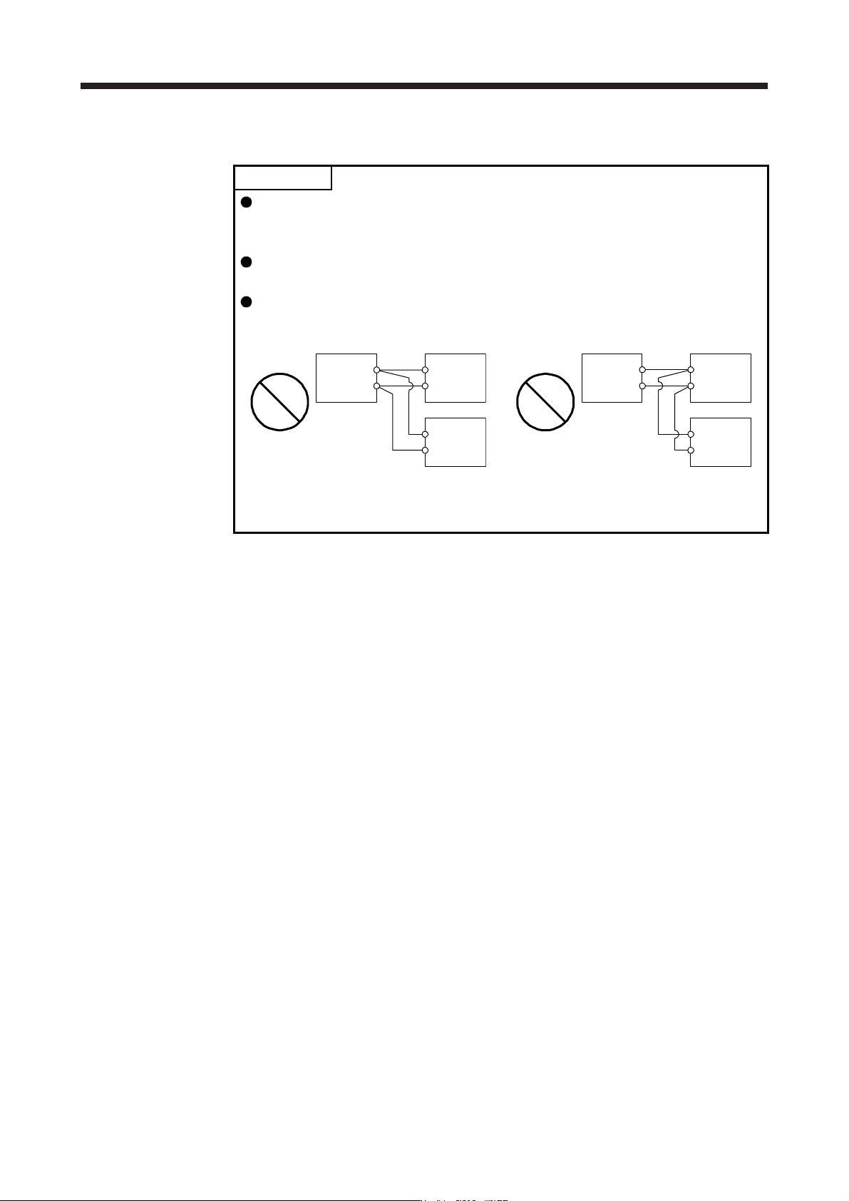
Do not connect the servo amplifier and brake units as below. Connect the cables
with a terminal block to distribute as indicated in this section.
N/-
P/+
Brake unit
Brake unit
Servo amplifier
P+
N-
N/-
P/+
Connecting two cables to
P+ and N- terminals
N/-
P/+
Brake unit
Brake unit
Servo amplifier
P+
N- N/-
P/+
Passing wiring
11. OPTIONS AND PERIPHERAL EQUIPMENT
11 - 32
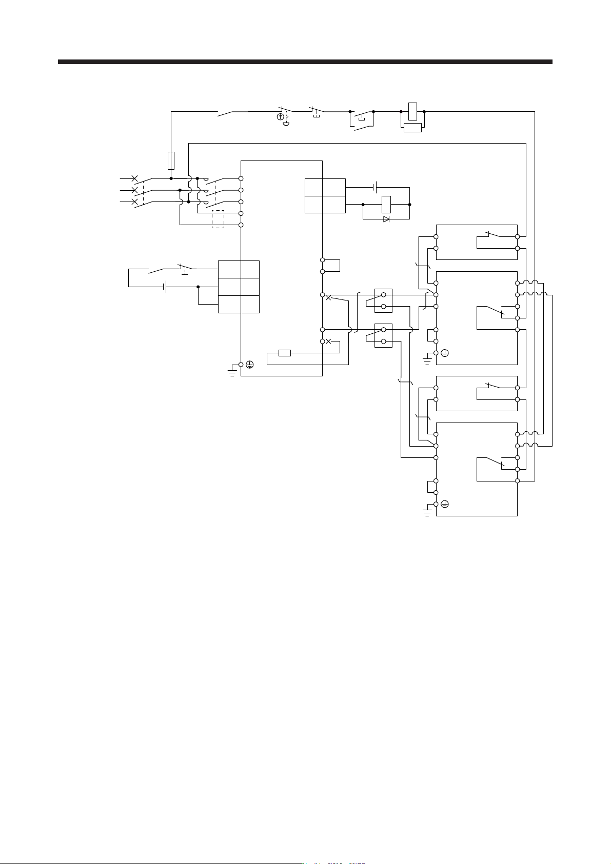
P3
P4
N-
C
Emergency stop switch
Servo amplifier
(Note 11)
(Note 13)
MC
MCCB
(Note 1)
Power
supply
L1
L2
L3
L11
L21
ALM
RA1
OFF
MC
ON
MC
SK
(Note 3)
P+
(Note 2)
(Note 7) N/-
P/+
BUE
SD
PR
B
C
A
SD
MSG
(Note 4)
(Note 6)
FR-BU2
FR-BR
P
PR
TH2
TH1(Note 5)
(Note 8)
(Note 10)
Terminal
block
(Note 9)
N/-
P/+
BUE
SD
PR
B
C
A
SD
MSG
(Note 4)
(Note 6)
FR-BU2
FR-BR
P
PR
TH2
TH1(Note 5)
(Note 8)
(Note 9)
CN3
(Note 12)
Main circuit
power supply
24 V DC (Note 14)
5
10
EM2
DICOM
DICOM
20
3
DOCOM
ALM15
CN3
RA1
24 V DC (Note 14)
Note 1. For the power supply specifications, refer to section 1.3.
2. When using the servo amplifier of 7 kW or less, make sure to disconnect the wiring of built-in regenerative resistor (5 kW or
less: P+ and D, 7 kW: P+ and C). For the servo amplifier of 11 kW to 22 kW, do not connect a supplied regenerative resistor to
the P+ and C terminals.
3. Between P3 and P4 is connected by default. When using the power factor improving DC reactor, remove the short bar
between P3 and P4. Refer to section 11.11 for details. Additionally, a power factor improving DC reactor and power factor
improving AC reactor cannot be used simultaneously.
4. Connect P/+ and N/- terminals of the brake unit to a correct destination. Incorrect connection destination results in servo
amplifier and brake unit malfunction.
5. Contact rating: 1b contact, 110 V AC, 5 A/220 V AC, 3 A
Normal condition: TH1-TH2 is conducting. Abnormal condition: TH1-TH2 is not conducting.
6. Contact rating: 230 V AC, 0.3 A/30 V DC, 0.3 A
Normal condition: B-C is conducting./A-C is not conducting. Abnormal condition: B-C is not conducting./A-C is conducting.
7. Do not connect more than one cable to each P+ and N- terminals of the servo amplifier.
8.
A
lways connect BUE and SD terminals. (factory-wired)
9. Connect MSG and SD terminals of the brake unit to a correct destination. Incorrect connection destination results in servo
amplifier and brake unit malfunction.
10. For connecting P+ and N- terminals of the servo amplifier to the terminal block, use the cable indicated in (4) (b) in this
section.
11. Depending on the main circuit voltage and operation pattern, bus voltage decreases, and that may cause the forced stop
deceleration to shift to the dynamic brake deceleration. When dynamic brake deceleration is not required, slow the time to turn
off the magnetic contactor.
12. Configure a circuit to turn off EM2 when the main circuit power is turned off to prevent an unexpected restart of the servo
amplifier.
13. When wires used for L11 and L21 are thinner than wires used for L1, L2, and L3, use a molded-case circuit breaker.
14. The illustration of the 24 V DC power supply is divided between input signal and output signal for convenience. However, they
can be configured by one.
11. OPTIONS AND PERIPHERAL EQUIPMENT
11 - 33
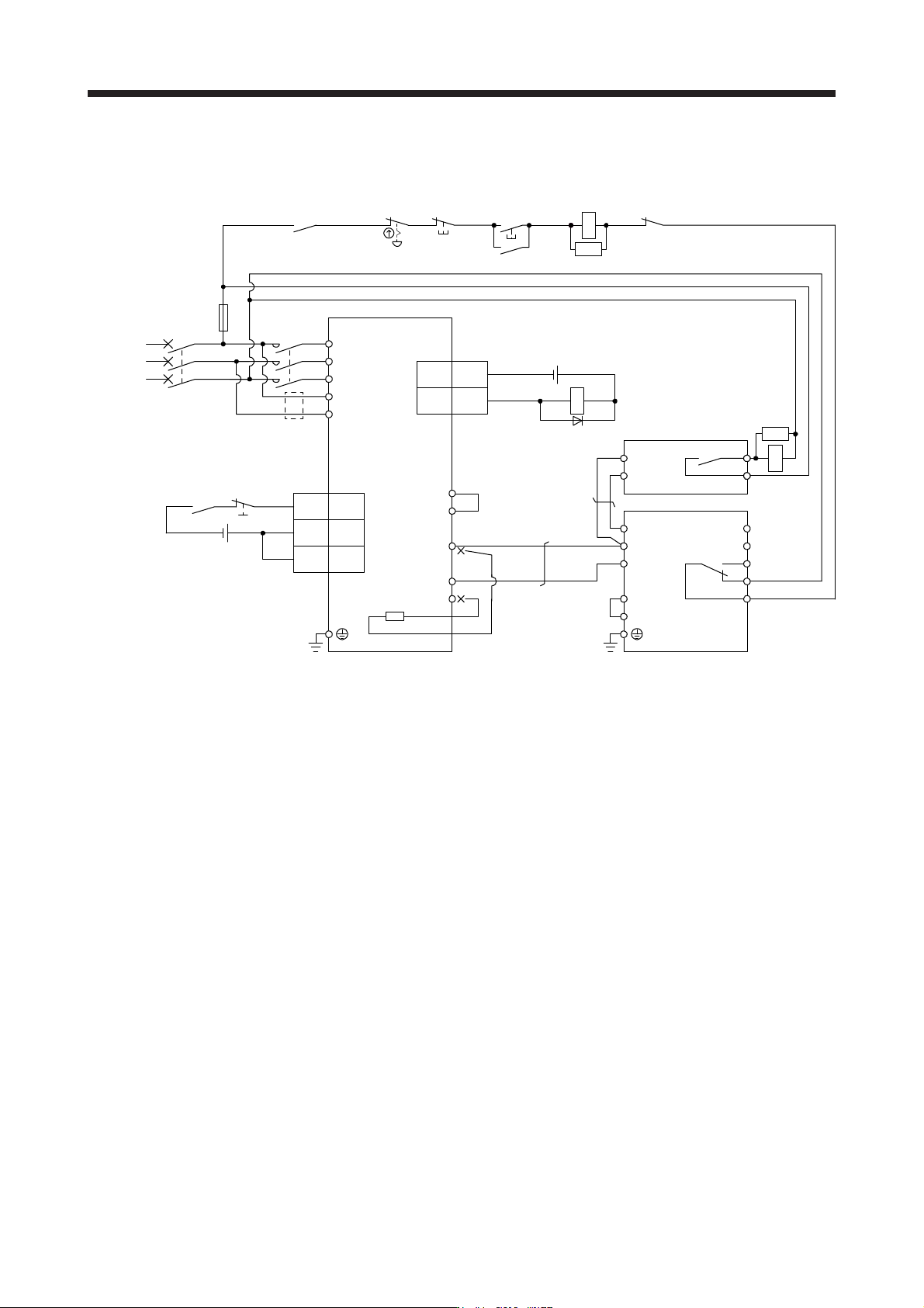
(2) Combination with MT-BR5-(H) resistor unit
(a) 200 V class
Emergency stop switch
Servo amplifier
(Note 9)
MC
MCCB
(Note 1)
Power
supply
L1
L2
L3
L11
L21
ALM
RA1
OFF
MC
ON
MC
SK
P3
P4
(Note 3)
P+
N-
C
(Note 2)
(Note 7)
(Note 11)
N/-
P/+
BUE
SD
PR
B
C
A
SD
MSG
(Note 4)
(Note 6)
FR-BU2
MT-BR5
P
PR
TH2
TH1(Note 5)
(Note 8)
15 ALM
EM2 20
24 V DC (Note 12)
DICOM
3
DOCOM
5
DICOM
10
CN3
CN3
RA1
(Note 10)
Main circuit
power supply
24 V DC (Note 12)
SK
RA2
RA2
Note 1. For the power suppl
y
specifications, refer to section 1.3.
2. Do not connect a supplied re
g
enerative resistor to the P+ and C terminals.
3. Between P3 and P4 is connected by default. When using the power factor improving DC reactor, remove the short bar
between P3 and P4. Refer to section 11.11 for details. Additionally, a power factor improving DC reactor and power factor
improvin
g
AC reactor cannot be used simultaneousl
y
.
4. Connect P/+ and N/- terminals of the brake unit to a correct destination. Incorrect connection destination results in servo
amplifier and brake unit malfunction.
5. Contact rating: 1a contact, 110 V AC, 5 A/220 V AC, 3 A
Normal condition: TH1-TH2 is not conductin
g
. Abnormal condition: TH1-TH2 is conductin
g
.
6. Contact rating: 230 V AC, 0.3 A/30 V DC, 0.3 A
Normal condition: B-C is conductin
g
./A-C is not conductin
g
. Abnormal condition: B-C is not conductin
g
./A-C is conductin
g
.
7. Do not connect more than one cable to each P+ and N- terminals of the servo amplifier.
8.
A
lwa
y
s connect BUE and SD terminals.
(
factor
y
-wired
)
9. Depending on the main circuit voltage and operation pattern, bus voltage decreases, and that may cause the forced stop
deceleration to shift to the dynamic brake deceleration. When dynamic brake deceleration is not required, slow the time to turn
off the ma
g
netic contactor.
10. Configure a circuit to turn off EM2 when the main circuit power is turned off to prevent an unexpected restart of the servo
amplifier.
11. When wires used for L11 and L21 are thinner than wires used for L1, L2, and L3, use a molded-case circuit breaker.
12. The illustration of the 24 V DC power supply is divided between input signal and output signal for convenience. However, they
can be confi
g
ured b
y
one.