sh030106u.pdf - 第361页
11. OPT ION S AND P ERI PHER AL EQU IPMENT 11 - 40 11.4 FR-R C-(H) power reg eneration conver ter POINT When usi ng the FR- RC-(H) power re generati on conv erter, set [ Pr. PA0 4] to "0 0 _ _" t o enab le EM1 …
11. OPTIONS AND PERIPHERAL EQUIPMENT
11 - 39
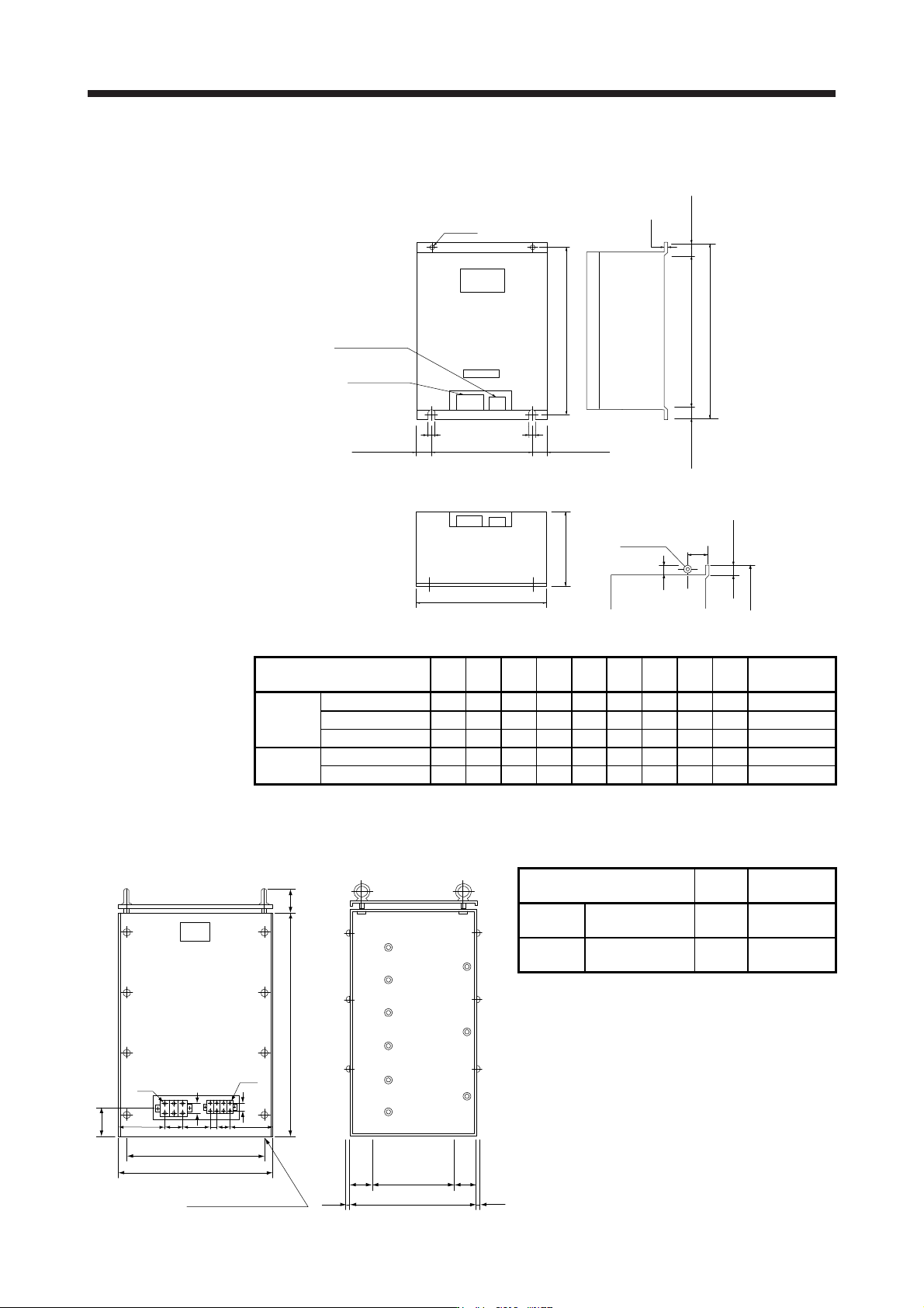
(2) FR-BR-(H) resistor unit
[Unit: mm]
H3 ± 1
H1 ± 3
Approx.
H2
Approx.
H2
D1
H ± 5
2-φC
Control circuit
terminal
Main circuit
terminal
W1 ± 1
Approx. 35
Approx. 35
C
C
W ± 5
D ± 5
(Note)
(Note)
Approx.
40
33
204
Eyebolt
For FR-BR-55K/FR-BR-H55K, an
eyebolt is placed on two locations.
(Refer to the following diagram. )
Note. Ventilation ports are provided on both sides and the top. The bottom is open.
Resistor unit W W1 H H1 H2 H3 D D1 C
Approximate
mass [kg]
200 V
class
FR-BR-15K 170 100 450 410 20 432 220 3.2 6 15
FR-BR-30K 340 270 600 560 20 582 220 4 10 30
FR-BR-55K 480 410 700 620 40 670 450 3.2 12 70
400 V
class
FR-BR-H30K 340 270 600 560 20 582 220 4 10 30
FR-BR-H55K 480 410 700 620 40 670 450 3.2 12 70
(3) MT-BR5-(H) resistor unit
[Unit: mm]
4φ15 mounting hole
30075 75
4507.5 7.5
M6
M4
193
189
480
510
85
85
800
37 60 2110
40
30
NP
Resistor unit
Resistance
Approximate
mass [kg]
200 V
class
MT-BR5-55K 2.0 Ω 50
400 V
class
MT-BR5-H75K 6.5 Ω 70

11. OPTIONS AND PERIPHERAL EQUIPMENT
11 - 40
11.4 FR-RC-(H) power regeneration converter
POINT
When using the FR-RC-(H) power regeneration converter, set [Pr. PA04] to
"0 0 _ _" to enable EM1 (Forced stop 1).
When using the FR-RC-(H) power regeneration converter, refer to "Power
Regeneration Converter FR-RC Instruction Manual (IB(NA)66330)".
When using the FR-RC-(H) power regeneration converter, set [Pr. PA02] to "_ _ 0 1" and set [Pr. PC20] to
"_ _ _ 1".
(1) Selection
The converters can continuously return 75% of the nominal regenerative power. They are applied to the
servo amplifiers of the 5 kW to 22 kW.
Power regeneration
converter
Nominal
regenerative
power [kW]
Servo amplifier
Nominal regenerative power [%]
50 75 100 150
0
500
300
200
100
50
30
20
Continuous energization time [s]
FR-RC-15K 15
MR-J4-500B(-RJ)
MR-J4-700B(-RJ)
MR-J4-11KB(-RJ)
MR-J4-15KB(-RJ)
FR-RC-30K 30
FR-RC-55K 55 MR-J4-22KB(-RJ)
FR-RC-H15K 15
MR-J4-500B4(-RJ)
MR-J4-700B4(-RJ)
FR-RC-H30K 30
MR-J4-11KB4(-RJ)
MR-J4-15KB4(-RJ)
FR-RC-H55K 55 MR-J4-22KB4(-RJ)
11. OPTIONS AND PERIPHERAL EQUIPMENT
11 - 41
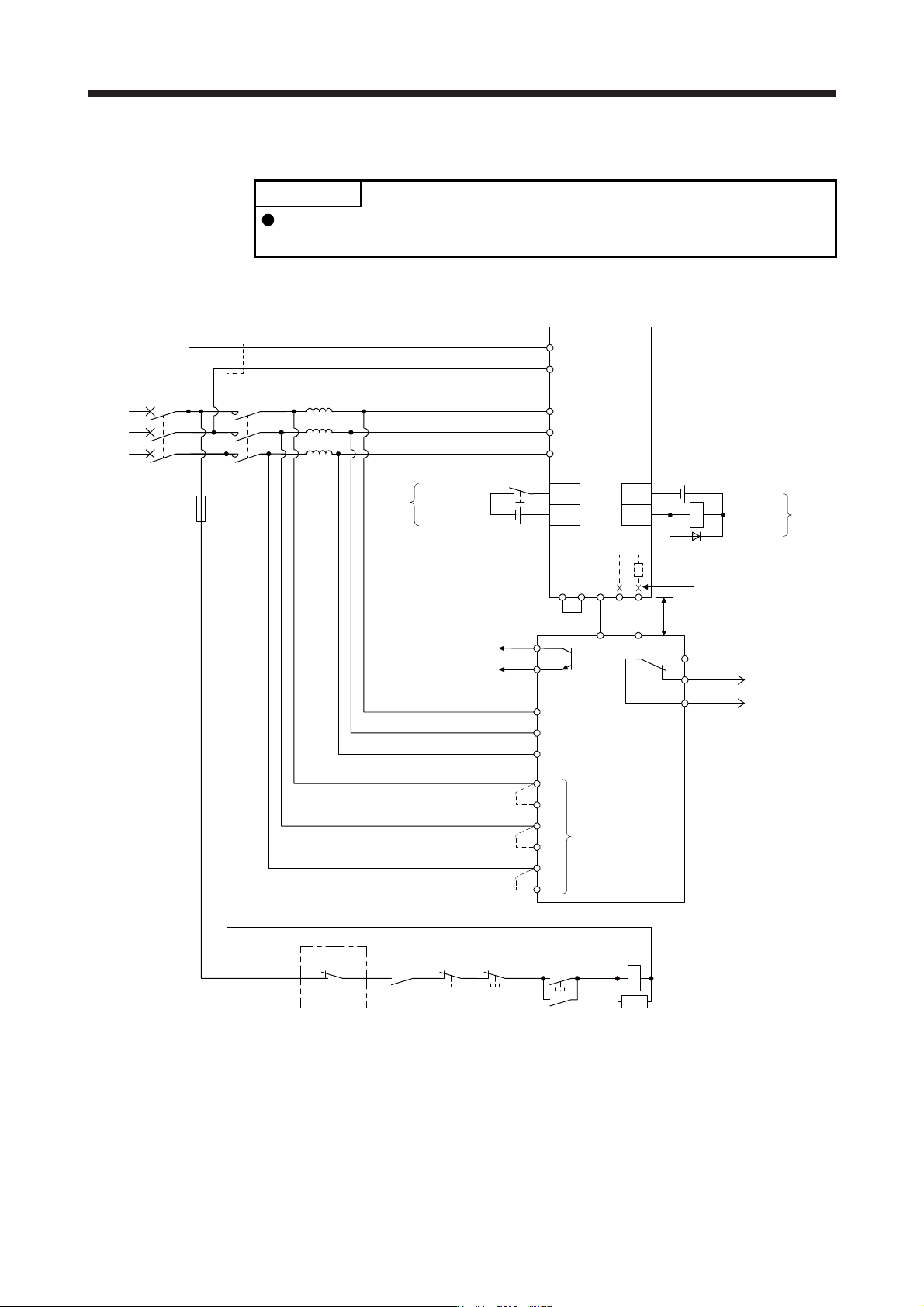
(2) Connection example
POINT
In this configuration, only the STO function is supported. The forced stop
deceleration function is not available.
(a) 200 V class
P3 P4
CN- P+
N/- P/+
RD
SE
MCMCCB
RX
R
SX
S
TX
T
R/L1
S/L2
T/L3
B
C
EM1
DICOM
CN3
DOCOM
ALM
CN3
RA
BC
FR-RC
ALM
RA
MC
MC
SK
L11
L21
L1
L2
L3
A
B
C
(Note 1)
Phase detection
terminals
(Note 4)
Ready
Alarm
output
RDY output
(Note 7)
(Note 5)
Power
supply
24 V DC (Note 9)
Malfunction
(Note 3)
Power factor
improving reactor
(Note 10)
Forced stop 1
(Note 6)
Power regeneration converter
FR-RC
Operation ready
OFF
ON
Forced stop 1
(Note 6)
Servo amplifier
(Note 2)
5 m or less
(Note 8)
(Note 8)
24 V DC (Note 9)