sh030106u.pdf - 第365页
11. OPT ION S AND P ERI PHER AL EQU IPMENT 11 - 44 (4) Mountin g hole machin ing di mensions The foll owing sho ws mo unting hole dim ensio ns for m ounti ng the h eat ge nerat ion area of the pow er regenerati on conver…
11. OPTIONS AND PERIPHERAL EQUIPMENT
11 - 43
Note 1. When not using the phase detection terminals, fit the jumpers across RX-R, SX-S and TX-T. If the jumpers remain removed,
the FR-RC-H will not operate.
2. When using the servo amplifier of 7 kW and 5 kW, make sure to disconnect the wiring of built-in regenerative resistor across
the P+ and C terminals. For the servo amplifier of 11 kW to 22 kW, do not connect a supplied regenerative resistor to the P+
and C terminals.
3. If ALM (Malfunction) output is disabled with the parameter, configure up the power supply circuit which switches off the
ma
g
netic contactor after detection of alarm occurrence on the controller side.
4. Between P3 and P4 is connected by default. When using the power factor improving DC reactor, remove the short bar
between P3 and P4. Refer to section 11.11 for details. Additionally, a power factor improving DC reactor and power factor
improvin
g
AC reactor cannot be used simultaneousl
y
.
5. For the power suppl
y
specifications, refer to section 1.3.
6. Set [Pr. PA04] to "0 0 _ _" to enable EM1 (Forced stop 1). Configure up the circuit which shuts off main circuit power with
external circuit at EM1
(
Forced stop 1
)
off.
7. When wires used for L11 and L21 are thinner than wires used for L1, L2, and L3, use a molded-case circuit breaker.
8. This dia
g
ram shows sink I/O interface. For source I/O interface, refer to section 3.8.3.
9. The illustration of the 24 V DC power supply is divided between input signal and output signal for convenience. However, they
can be confi
g
ured b
y
one.
10. For selection of power factor improving AC reactors, refer to "Power Regeneration Converter FR-RC Instruction Manual
(
IB
(
NA
)
66330
)
".
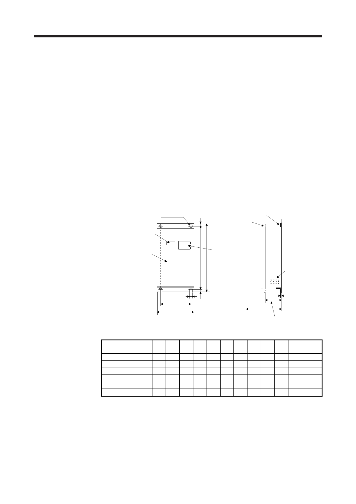
(3) Dimensions
AA
A
C
F
K
EE
BA
B
E
D
2-φD hole
Rating plate
Front cover
Display
panel
window
Mounting foot (removable)
Mounting foot
(movable)
Cooling fan
Heat generation area outside mounting dimension
[Unit: mm]
Power regeneration
converter
AAABBAC D EEE K F
Approximate
mass [kg]
FR-RC-15K 270 200 450 432 195 10 10 8 3.2 87 19
FR-RC-30K 340 270 600 582 195 10 10 8 3.2 90 31
FR-RC-55K 480 410 700 670 250 12 15 15 3.2 135 55
FR-RC-H15K
340 270 600 582 195 10 10 8 3.2 90 31
FR-RC-H30K
FR-RC-H55K 480 410 700 670 250 12 15 15 3.2 135 55
11. OPTIONS AND PERIPHERAL EQUIPMENT
11 - 44
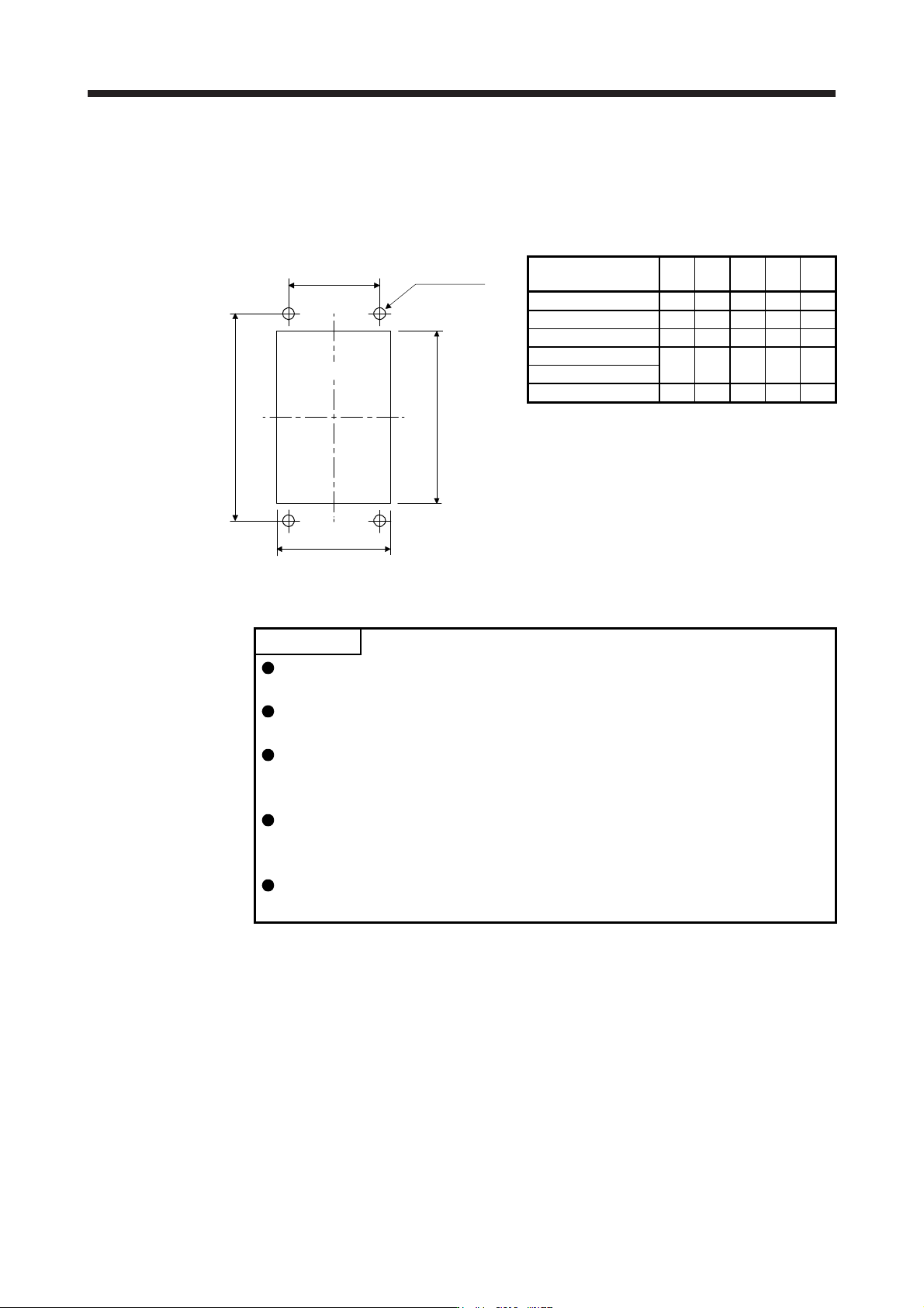
(4) Mounting hole machining dimensions
The following shows mounting hole dimensions for mounting the heat generation area of the power
regeneration converter outside a cabinet as measures against heat generation when the converter is
mounted in an enclosed type cabinet.
[Unit: mm]
(AA)
(BA)
b
a
(2-φD hole)
(Mounting hole)
Power regeneration
converter
a b D AA BA
FR-RC-15K 260 412 10 200 432
FR-RC-30K 330 562 10 270 582
FR-RC-55K 470 642 12 410 670
FR-RC-H15K
330 562 10 270 582
FR-RC-H30K
FR-RC-H55K 470 642 12 410 670
11.5 FR-CV-(H) power regeneration common converter
POINT
For details of the power regeneration common converter FR-CV-(H), refer to the
FR-CV Installation Guide (IB(NA)0600075).
Do not supply power to the main circuit power supply terminals (L1/L2/L3) of the
servo amplifier. Otherwise, the servo amplifier and FR-CV-(H) will malfunction.
Connect the DC power supply between the FR-CV-(H) and servo amplifier with
correct polarity. Connection with incorrect polarity will fail the FR-CV-(H) and
servo amplifier.
Two or more FR-CV-(H)s cannot be installed to improve regeneration capability.
Two or more FR-CV-(H)s cannot be connected to the same DC power supply
line.
When using FR-CV-(H), set [Pr. PA04] to "0 0 _ _" to enable EM1 (Forced stop
1).
When using the FR-CV-(H) power regeneration common converter, set [Pr. PA02] to "_ _ 0 1" and set [Pr.
PC20] to "_ _ _ 1".
11. OPTIONS AND PERIPHERAL EQUIPMENT
11 - 45
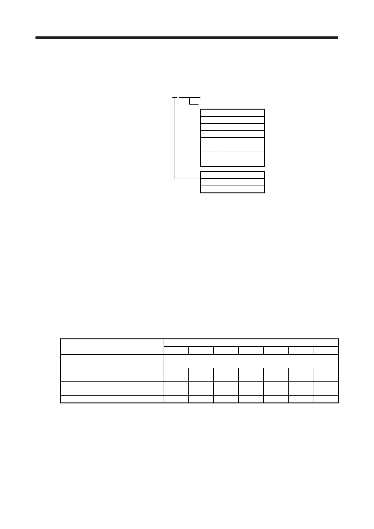
11.5.1 Model designation
The following describes what each block of a model name indicates. Not all combinations of the symbols are
available.
Capacity
Symbol Capacity [kW]
22K 22
30K 30
37K 37
55K 55
Symbol Voltage class
H 400 V class
7.5K 7.5
11K 11
15K 15
None 200 V class
RCFHV57--.K
11.5.2 Selection
(1) 200 V class
FR-CV power regeneration common converter can be used for the 200 V class servo amplifier of 100 W
to 22 kW. The following shows the restrictions on using the FR-CV.
(a) Up to six servo amplifiers can be connected to one FR-CV.
(b) FR-CV capacity [W] ≥ Total of rated capacities [W] × 2 of servo amplifiers connected to FR-CV
(c) The total of used servo motor rated currents should be equal to or less than the applicable current
[A] of the FR-CV.
(d) Among the servo amplifiers connected to the FR-CV, the rated capacity of the servo amplifier with
the maximum rated capacity should be equal to or less the value of than "Maximum servo amplifier
capacity" in the following table.
The following table lists the restrictions.
Item
FR-CV-_
7.5K 11K 15K 22K 30K 37K 55K
Maximum number of connected servo
amplifiers
6
Total of connectable servo amplifier
capacities [kW]
3.75 5.5 7.5 11 15 18.5 27.5
Total of connectable servo motor rated
currents [A]
33 46 61 90 115 145 215
Maximum servo amplifier capacity [kW] 3.5 5 7 11 15 15 22