sh030106u.pdf - 第373页
11. OPT ION S AND P ERI PHER AL EQU IPMENT 11 - 52 Power regenerati on common convert er FR-CV- H_ Item 7.5K 11K 15K 22K 30K 37K 55K Total of connect able servo ampl ifier capaciti es [kW] 3.75 5.5 7.5 11 15 185 27. 5 Ma…
11. OPTIONS AND PERIPHERAL EQUIPMENT
11 - 51
(5) Other precautions
(a) When using the FR-CV-(H), always install the dedicated stand-alone reactor (FR-CVL-(H)). Do not
use the power factor improving AC reactor (FR-HAL-(H)) or power factor improving DC reactor (FR-
HEL-(H)).
(b) The inputs/outputs (main circuits) of the FR-CV-(H) and servo amplifiers include high-frequency
components and may provide electromagnetic wave interference to communication equipment (such
as AM radios) used near them. In this case, interference can be reduced by installing the radio noise
filter (FR-BIF(-H)) or line noise filter (FR-BSF01, FR-BLF).
(c) The overall wiring length for connection of the DC power supply between the FR-CV-(H) and servo
amplifiers should be 5 m or less, and the wiring must be twisted.
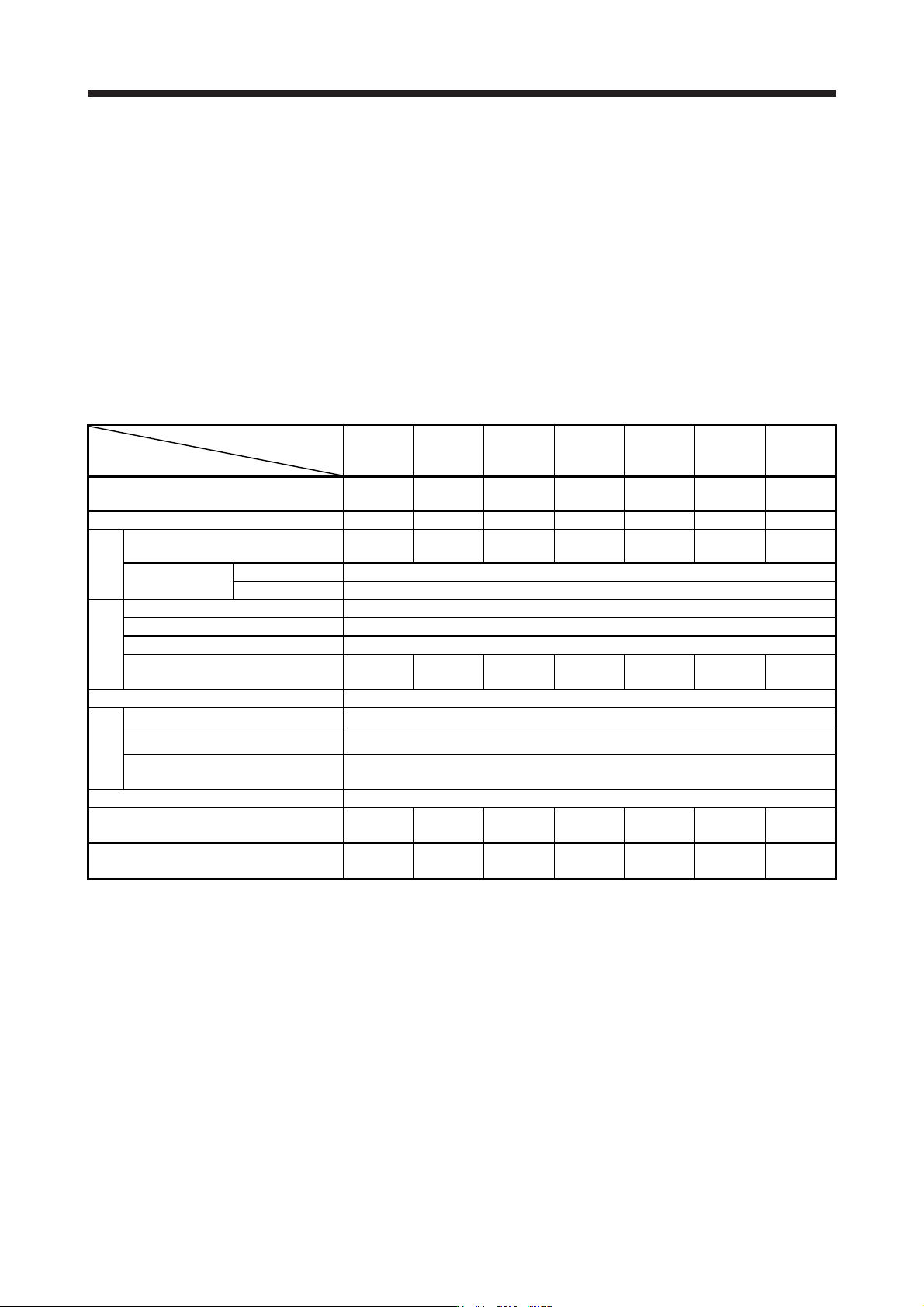
(6) Specifications
Power regeneration common
converter FR-CV-_
Item
7.5K 11K 15K 22K 30K 37K 55K
Total of connectable servo amplifier
capacities
[kW] 3.75 5.5 7.5 11 15 18.5 27.5
Maximum servo amplifier capacity [kW] 3.5 5 7 11 15 15 22
Output
Total of connectable servo
motor rated currents
[A] 33 46 61 90 115 145 215
Regenerative
braking torque
Short-time rating Total capacity of applicable servo motors, 300% torque, 60 s (Note 1)
Continuous rating 100% torque
Power
Rated input AC voltage/frequency 3-phase 200 V AC to 220 V AC, 50 Hz, 200 V AC to 230 V AC, 60 Hz
Permissible AC voltage fluctuation 3-phase 170 V AC to 242 V AC, 50 Hz, 170 V AC to 253 V AC, 60 Hz
Permissible frequency fluctuation ±5%
Power supply capacity
(Note 2)
[kVA] 17 20 28 41 52 66 100
IP rating (JEM 1030), cooling method Open type (IP00), forced cooling
Environment
Ambient temperature -10 ˚C to 50 ˚C (non-freezing)
Ambient humidity 5 %RH to 90 %RH (non-condensing)
Ambience
Indoors (no direct sunlight), free from corrosive gas, flammable gas,
oil mist, dust, and dirt
Altitude, vibration resistance 1000 m or less above sea level, 5.9 m/s
2
Molded-case circuit breaker or earth-
leakage current breaker
30AF
30A
50AF
50A
100AF
75A
100AF
100A
125AF
125A
125AF
125A
225AF
175A
Magnetic contactor
S-N20
S-T21
S-N35
S-T35
S-N50
S-T50
S-N65
S-T65
S-N80
S-T80
S-N95
S-T100
S-N125
11. OPTIONS AND PERIPHERAL EQUIPMENT
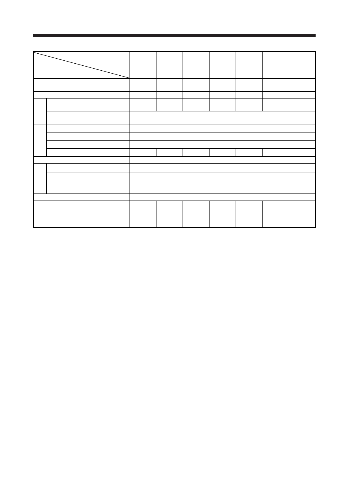
11 - 52
Power regeneration
common converter
FR-CV-H_
Item
7.5K 11K 15K 22K 30K 37K 55K
Total of connectable servo amplifier
capacities
[kW] 3.75 5.5 7.5 11 15 185 27.5
Maximum servo amplifier capacity [kW] 3.5 5 7 11 15 15 22
Output
Total of connectable servo
motor rated currents
[A] 17 23 31 43 57 71 110
Regenerative
braking torque
Short-time rating Total capacity of applicable servo motors, 300% torque, 60 s (Note 1)
Continuous rating 100% torque
Power supply
Rated input AC voltage/frequency 3-phase 380 V AC to 480 V AC, 50 Hz/60 Hz
Permissible AC voltage fluctuation 3-phase 323 V AC to 528 V AC, 50 Hz/60 Hz
Permissible frequency fluctuation ±5%
Power supply capacity (Note 2) [kVA] 17 20 28 41 52 66 100
IP rating (JEM 1030), cooling method Open type (IP00), forced cooling
Environment
Ambient temperature -10 °C to 50 °C (non-freezing)
Ambient humidity 5 %RH to 90 %RH (non-condensing)
Ambience
Indoors (no direct sunlight), free from corrosive gas, flammable gas,
oil mist, dust, and dirt
Altitude, vibration resistance 1000 m or less above sea level, 5.9 m/s
2
Molded-case circuit breaker or earth-leakage
current breaker
30AF
15A
30AF
20A
30AF
30A
50AF
50A
60AF
60A
100AF
75A
100AF
100A
Magnetic contactor
S-N20
S-T21
S-N20
S-T21
S-N20
S-T21
S-N25
S-T25
S-N35
S-T35
S-N50
S-T50
S-N65
S-T65
Note 1. This is the time when the protective function of the FR-CV-(H) is activated. The protective function of the servo amplifier is
activated in the time indicated in section 10.1.
2. The specified value is the power supply capacity of FR-CV-(H). The total power supply capacities of the connected servo
amplifiers are actuall
y
required.
11. OPTIONS AND PERIPHERAL EQUIPMENT
11 - 53
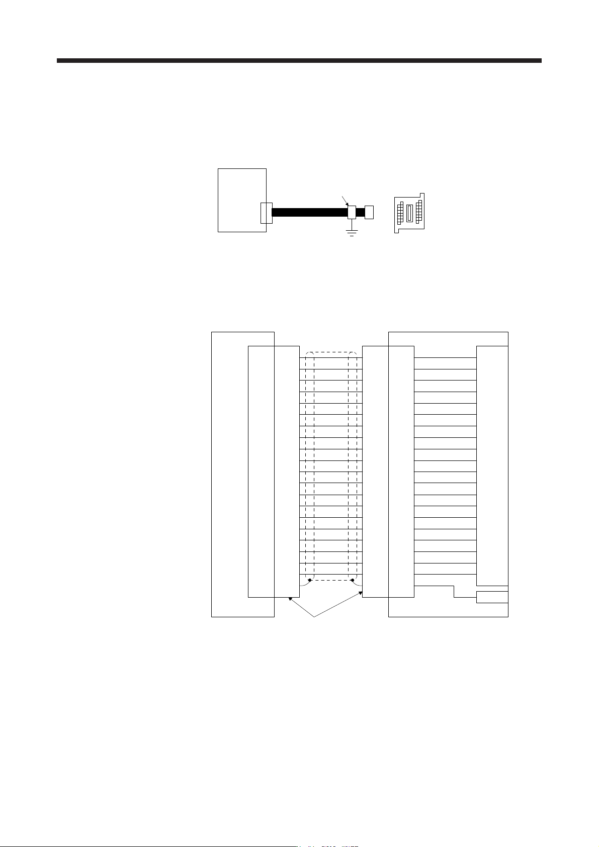
11.6 Junction terminal block PS7DW-20V14B-F (recommended)
(1) Usage
Always use the junction terminal block (PS7W-20V14B-F (Toho Technology)) with the option cable (MR-
J2HBUS_M) as a set. A connection example is shown below.
Junction terminal bloc
k
PS7DW-20V14B-F
CN3
MR-J2HBUS_M
Servo amplifie
r
Cable clamp
(AERSBAN-ESET)
Ground the junction terminal block cable on the junction terminal block side with the supplied cable
clamp fitting (AERSBAN-ESET). For the use of the cable clamp fitting, refer to section 11.14, (2) (c).
(2) Connection of MR-J2HBUS_M cable and junction terminal block
LG
DI1
1
2
DOCOM
MO1
3
4
LZ 8
LB 7
9
SD
Shell
(Note) MR-J2HBUS_M
INP
5
6
10DICOM
DICOM
LA
LG
DI2
11
12
MBR
MO2
13
14
LZR 18
LBR 17
19DI3
15
16
20EM2
ALM
LAR
Shell Shell Shell
1
2
3
4
8
7
9
5
6
10
11
12
13
14
18
17
19
15
16
20
1
2
3
4
8
7
9
5
6
10
11
12
13
14
18
17
19
15
16
20
1
2
3
4
8
7
9
5
6
10
11
12
13
14
18
17
19
15
16
20
LG
DI1
DOCOM
MO1
LZ
LB
SD
INP
DICOM
DICOM
LA
LG
DI2
MBR
MO2
LZR
LBR
DI3
EM2
ALM
LAR
E
Servo amplifier
CN3
Junction terminal block
PS7DW-20V14B-F
Connector: 52316-2019 (Molex)
Shell kit: 52370-2070 (Molex)
CN
Terminal block
1
2
3
4
8
7
9
5
6
10
11
12
13
14
18
17
19
15
16
20
Note. Symbol indicating cable length is put in _.
05: 0.5 m
1: 1 m
5: 5 m