sh030106u.pdf - 第375页
11. OPT ION S AND P ERI PHER AL EQU IPMENT 11 - 54 (3) Dimensio ns of j unction termin al bloc k [Unit: mm] M3 × 6L M3 × 5L 36.5 27.8 18.8 7.62 44.11 54 63 φ 4.5 4.5 5 4 60 50 9.3 27 TB.E ( φ 6) 1.42 6.2 11.7 MR C onfigu…
11. OPTIONS AND PERIPHERAL EQUIPMENT
11 - 53
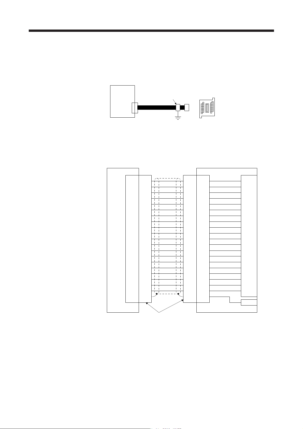
11.6 Junction terminal block PS7DW-20V14B-F (recommended)
(1) Usage
Always use the junction terminal block (PS7W-20V14B-F (Toho Technology)) with the option cable (MR-
J2HBUS_M) as a set. A connection example is shown below.
Junction terminal bloc
k
PS7DW-20V14B-F
CN3
MR-J2HBUS_M
Servo amplifie
r
Cable clamp
(AERSBAN-ESET)
Ground the junction terminal block cable on the junction terminal block side with the supplied cable
clamp fitting (AERSBAN-ESET). For the use of the cable clamp fitting, refer to section 11.14, (2) (c).
(2) Connection of MR-J2HBUS_M cable and junction terminal block
LG
DI1
1
2
DOCOM
MO1
3
4
LZ 8
LB 7
9
SD
Shell
(Note) MR-J2HBUS_M
INP
5
6
10DICOM
DICOM
LA
LG
DI2
11
12
MBR
MO2
13
14
LZR 18
LBR 17
19DI3
15
16
20EM2
ALM
LAR
Shell Shell Shell
1
2
3
4
8
7
9
5
6
10
11
12
13
14
18
17
19
15
16
20
1
2
3
4
8
7
9
5
6
10
11
12
13
14
18
17
19
15
16
20
1
2
3
4
8
7
9
5
6
10
11
12
13
14
18
17
19
15
16
20
LG
DI1
DOCOM
MO1
LZ
LB
SD
INP
DICOM
DICOM
LA
LG
DI2
MBR
MO2
LZR
LBR
DI3
EM2
ALM
LAR
E
Servo amplifier
CN3
Junction terminal block
PS7DW-20V14B-F
Connector: 52316-2019 (Molex)
Shell kit: 52370-2070 (Molex)
CN
Terminal block
1
2
3
4
8
7
9
5
6
10
11
12
13
14
18
17
19
15
16
20
Note. Symbol indicating cable length is put in _.
05: 0.5 m
1: 1 m
5: 5 m
11. OPTIONS AND PERIPHERAL EQUIPMENT
11 - 54
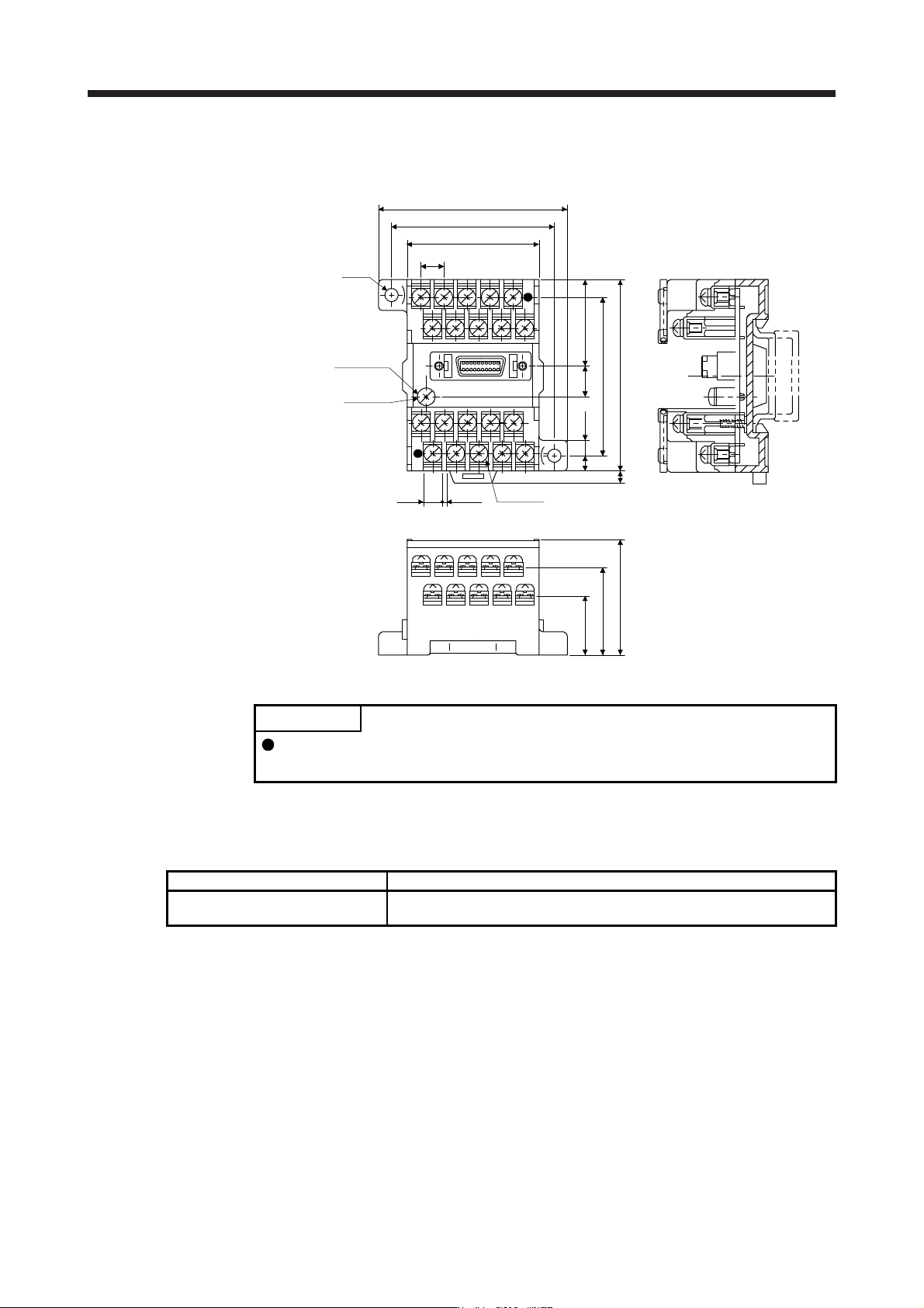
(3) Dimensions of junction terminal block
[Unit: mm]
M3 × 6L
M3 × 5L
36.5
27.8
18.8
7.62
44.11
54
63
φ4.5
4.5
5
4
60
50
9.3 27
TB.E (φ6)
1.426.2
11.7 MR Configurator2
POINT
The MR-J4-_B_-RJ servo amplifier is supported with software version 1.19V or
later.
11.7.1 Engineering software
The following engineering software is available with this servo amplifier.
Engineering software Installation guide
MR Configurator2 SW1DNC-MRC2-_
MR Configurator2 SW1DNC-MRC2-_ INSTALLATION GUIDE
(IB(NA)0300163ENG)
For the engineering software specifications and system configuration, refer to the installation guide.

11. OPTIONS AND PERIPHERAL EQUIPMENT
11 - 55
11.7.2 Precautions for using USB communication function
Note the following to prevent an electric shock and malfunction of the servo amplifier.
(1) Power connection of personal computers
Connect your personal computer with the following procedures.
(a) When you use a personal computer with AC power supply
1) When using a personal computer with a three-core power plug or power plug with grounding wire,
use a three-pin socket or ground the grounding wire.
2) When your personal computer has two-core plug and has no grounding wire, connect the
personal computer to the servo amplifier with the following procedures.
a) Disconnect the power plug of the personal computer from an AC power socket.
b) Check that the power plug was disconnected and connect the device to the servo amplifier.
c) Connect the power plug of the personal computer to the AC power socket.
(b) When you use a personal computer with battery
You can use as it is.
(2) Connection with other devices using servo amplifier communication function
When the servo amplifier is charged with electricity due to connection with a personal computer and the
charged servo amplifier is connected with other devices, the servo amplifier or the connected devices
may malfunction. Connect the servo amplifier and other devices with the following procedures.
(a) Shut off the power of the device for connecting with the servo amplifier.
(b) Shut off the power of the servo amplifier which was connected with the personal computer and check
the charge lamp is off.
(c) Connect the device with the servo amplifier.
(d) Turn on the power of the servo amplifier and the device.