sh030106u.pdf - 第379页
11. OPT ION S AND P ERI PHER AL EQU IPMENT 11 - 58 (a) Batter y insta llation a nd rem oval proc edure 1) Installat ion pr ocedur e POINT For the ser vo amp lifier with a bat tery ho lder on the bott om, it is not poss i…
11. OPTIONS AND PERIPHERAL EQUIPMENT
11 - 57
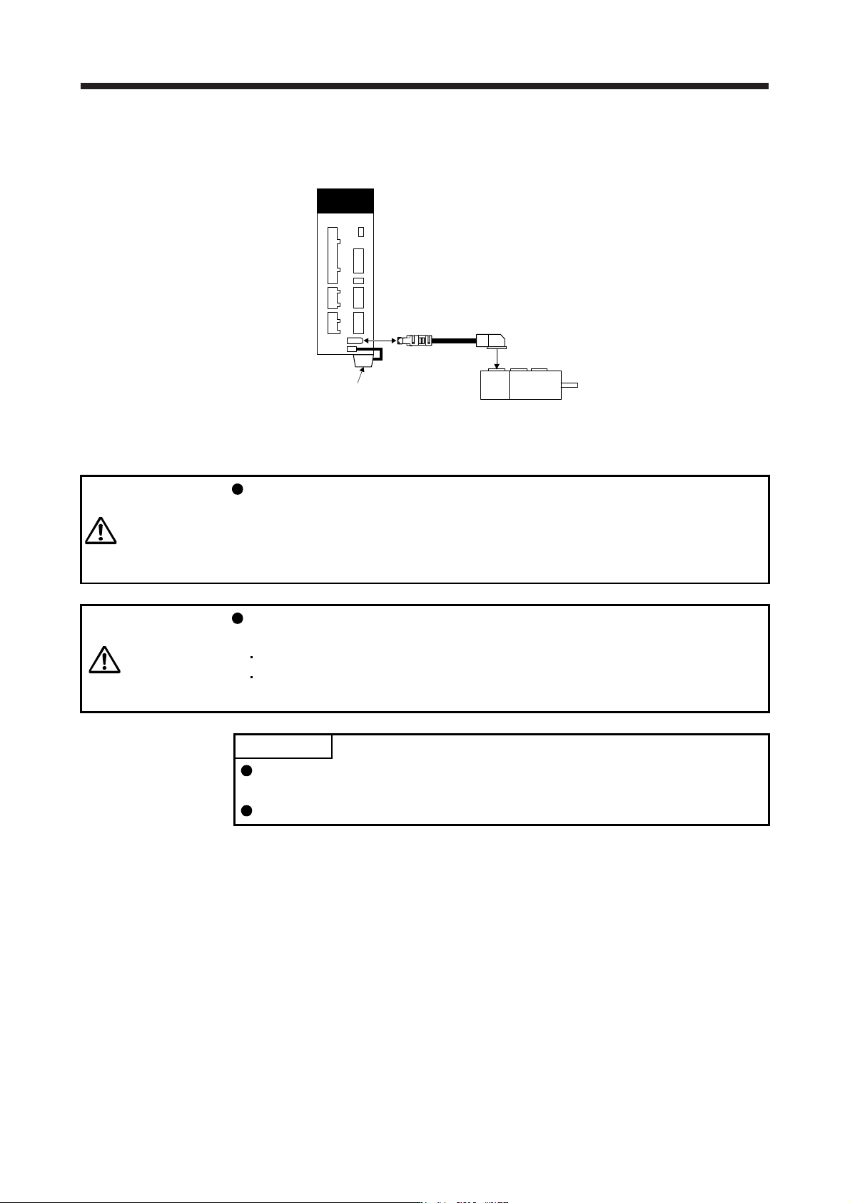
(2) Battery mounting
Connect as follows.
CN2
CN4
Servo amplifier
Encoder cable
Servo motor
MR-BAT6V1SET
(3) Battery replacement procedure
WARNING
Before replacing a battery, turn off the main circuit power and wait for 15 minutes
or longer until the charge lamp turns off. Then, check the voltage between P+ and
N- with a voltage tester or others. Otherwise, an electric shock may occur. In
addition, when confirming whether the charge lamp is off or not, always confirm it
from the front of the servo amplifier.
CAUTION
The internal circuits of the servo amplifier may be damaged by static electricity.
Always take the following precautions.
Ground human body and work bench.
Do not touch the conductive areas, such as connector pins and electrical parts,
directly by hand.
POINT
Replacing battery with the control circuit power off will erase the absolute
position data.
Before replacing batteries, check that the new battery is within battery life.
Replace the battery while only control circuit power is on. Replacing battery with the control circuit power
on triggers [AL. 9F.1 Low battery]. However, the absolute position data will not be erased.
11. OPTIONS AND PERIPHERAL EQUIPMENT
11 - 58
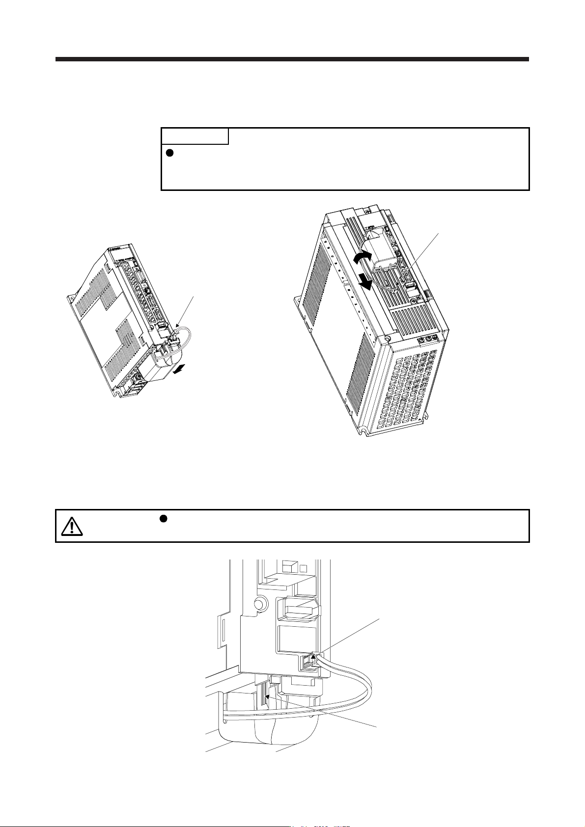
(a) Battery installation and removal procedure
1) Installation procedure
POINT
For the servo amplifier with a battery holder on the bottom, it is not possible to
wire for the earth with the battery installed. Insert the battery after executing the
earth wiring of the servo amplifier.
Install a battery, and insert the
plug into the CN4 connector.
Install a battery, and insert the
plug into the CN4 connector.
For the servo amplifier
with a battery holder on the bottom
For the servo amplifier
with a battery holder on the front
2) Removal procedure
CAUTION
Pulling out the connector of the battery without the lock release lever pressed may
damage the CN4 connector of the servo amplifier or the connector of the battery.
While pressing the lock release lever,
pull out the connector.
While pressing the lock release lever, slide
the battery case toward you.
11. OPTIONS AND PERIPHERAL EQUIPMENT
11 - 59
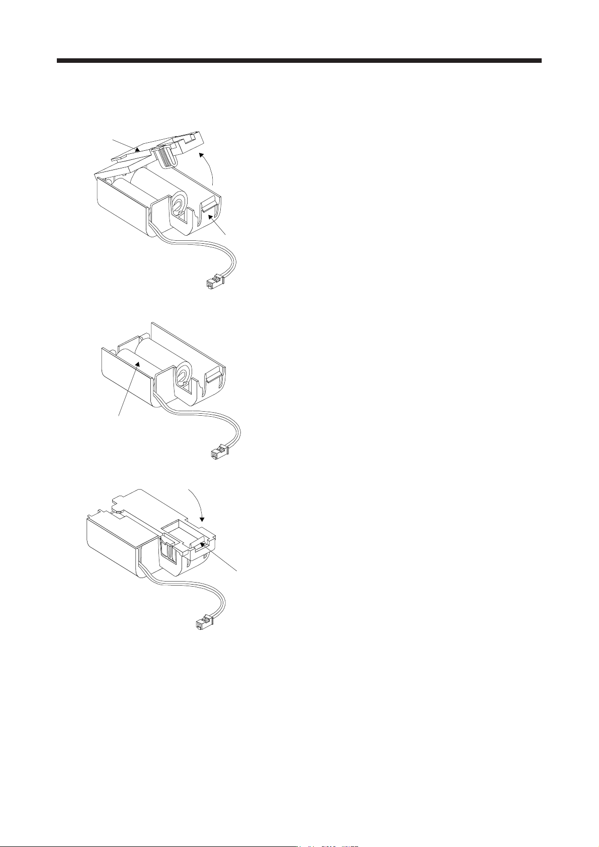
(4) Replacement procedure of the built-in battery
When the MR-BAT6V1SET reaches the end of its life, replace the built-in MR-BAT6V1 battery.
Cover
Locking part
1) While pressing the locking part, open the cover.
MR-BAT6V1
2) Replace the battery with a new MR-BAT6V1.
Projection
3) Press the cover until it is fixed with the projection of
the locking part to close the cover.