sh030106u.pdf - 第384页
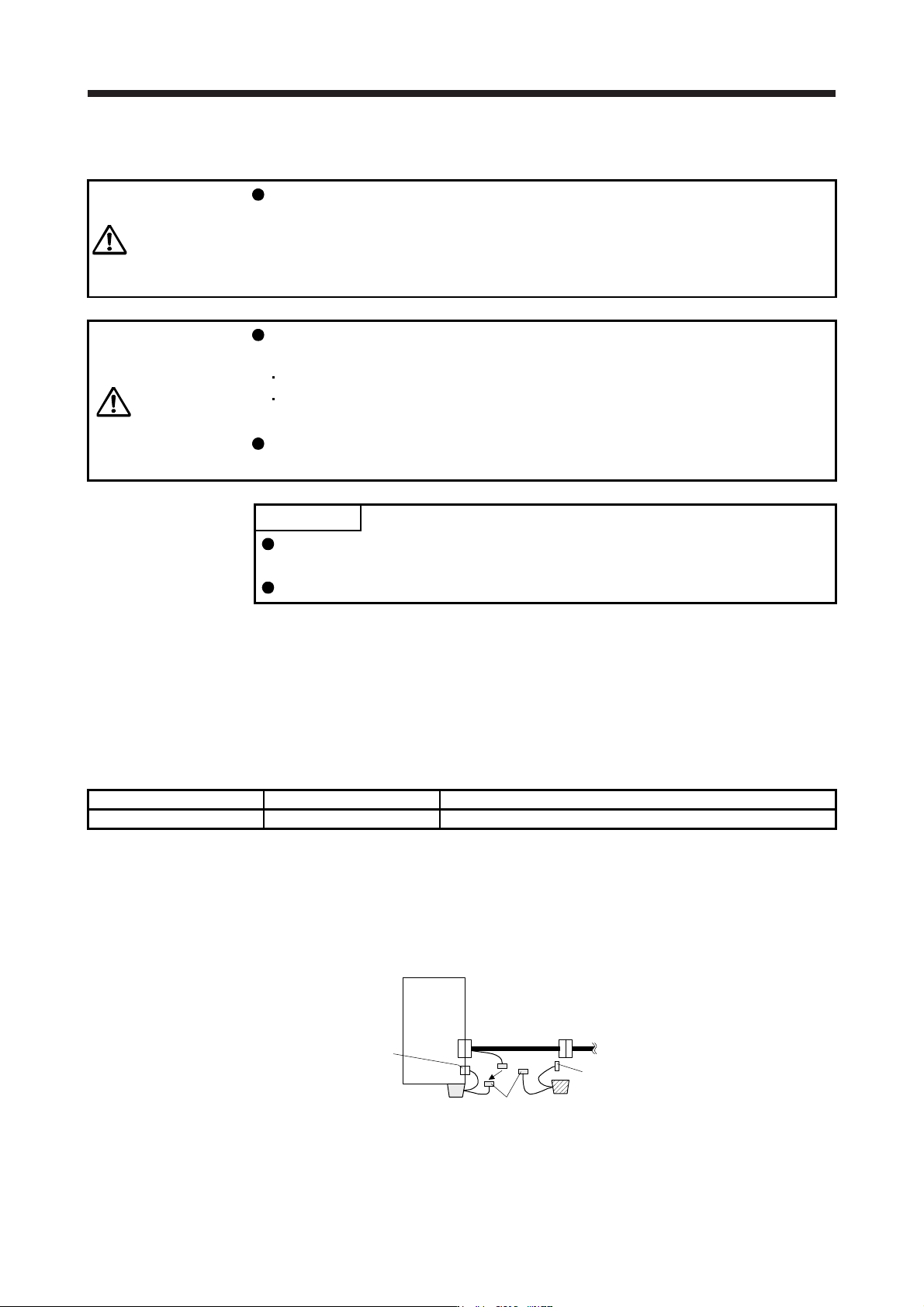
11. OPT ION S AND P ERI PHER AL EQU IPMENT 11 - 63 2) Connec t the conn ector for branch c able co nnect ion (blac k) of the new MR- BAT6V 1BJ. MR-BT6VCBL03M CN4 CN2 Servo amplifier Old MR-BAT6V1BJ New MR-BAT6V1BJ Orange…
11. OPTIONS AND PERIPHERAL EQUIPMENT
11 - 62
(6) Battery replacement procedure
WARNING
Before replacing a battery, turn off the main circuit power and wait for 15 minutes
or longer until the charge lamp turns off. Then, check the voltage between P+ and
N- with a voltage tester or others. Otherwise, an electric shock may occur. In
addition, when confirming whether the charge lamp is off or not, always confirm it
from the front of the servo amplifier.
CAUTION
The internal circuits of the servo amplifier may be damaged by static electricity.
Always take the following precautions.
Ground human body and work bench.
Do not touch the conductive areas, such as connector pins and electrical parts,
directly by hand.
The battery built in MR-BAT6V1BJ cannot be replaced. Do not disassemble the
MR-BAT6V1BJ. Otherwise, it may cause a malfunction.
POINT
To replace the MR-BAT6V1BJ, follow the procedures given in this section to
avoid erasing absolute position data.
Before replacing batteries, check that the new battery is within battery life.
For MR-BAT6V1BJ, the battery can be replaced with the control circuit power supply off.
(a) Battery installation and removal procedure
The battery installation and removal procedure to the servo amplifier are the same as for the MR-
BAT6V1SET battery. Refer to (3) of section 11.8.2.
(b) Preparation for replacing MR-BAT6V1BJ
Prepare a new MR-BAT6V1BJ as follows.
Model Number and use Remark
MR-BAT6V1BJ 1 for replacement Battery within two years from the production date.
(c) Procedures of replacing MR-BAT6V1BJ
Replace the product as follows regardless of on/off of the control circuit power supply. When it is
replaced with other procedures, the absolute position data will be erased.
1) Remove the connector for branch cable connection (black) of the old MR-BAT6V1BJ.
MR-BT6VCBL03M
CN4
CN2
Servo amplifier
Old MR-BAT6V1BJ
New MR-BAT6V1BJ
Orange
Orange
Black
11. OPTIONS AND PERIPHERAL EQUIPMENT
11 - 63
2) Connect the connector for branch cable connection (black) of the new MR-BAT6V1BJ.
MR-BT6VCBL03M
CN4
CN2
Servo amplifier
Old MR-BAT6V1BJ
New MR-BAT6V1BJ
Orange
Orange
Black
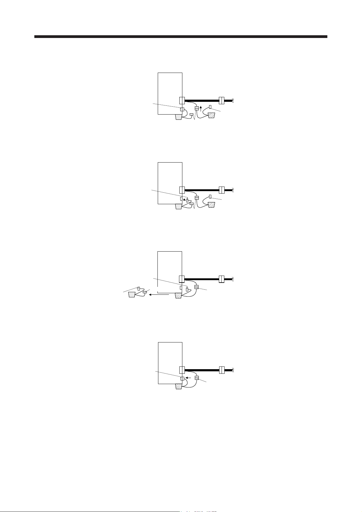
3) Remove the connector for servo amplifier (orange) of the old MR-BAT6V1BJ. When the control
circuit power supply is on, performing 3) without [AL. 9F.1 Low battery] will trigger [AL. 9F.1].
MR-BT6VCBL03M
CN4
CN2
Servo amplifier
Old MR-BAT6V1BJ
New MR-BAT6V1BJ
Orange
Orange
Black
4) Remove the old MR-BAT6V1BJ from servo amplifier and mount the new MR-BAT6V1BJ. When
the control circuit power supply is on, [AL. 9F.1] will occur after 3).
MR-BT6VCBL03M
CN4
CN2
Servo amplifier
New MR-BAT6V1BJ
Old MR-BAT6V1BJ
Orange
Orange
Black
Black
5) Mount the connector for servo amplifier (orange) of the new MR-BAT6V1BJ. When the control
circuit power supply is on, [AL. 9F.1] will be canceled.
MR-BT6VCBL03M
CN4
CN2
Servo amplifier
New MR-BAT6V1BJ
Orange
Black
11. OPTIONS AND PERIPHERAL EQUIPMENT
11 - 64
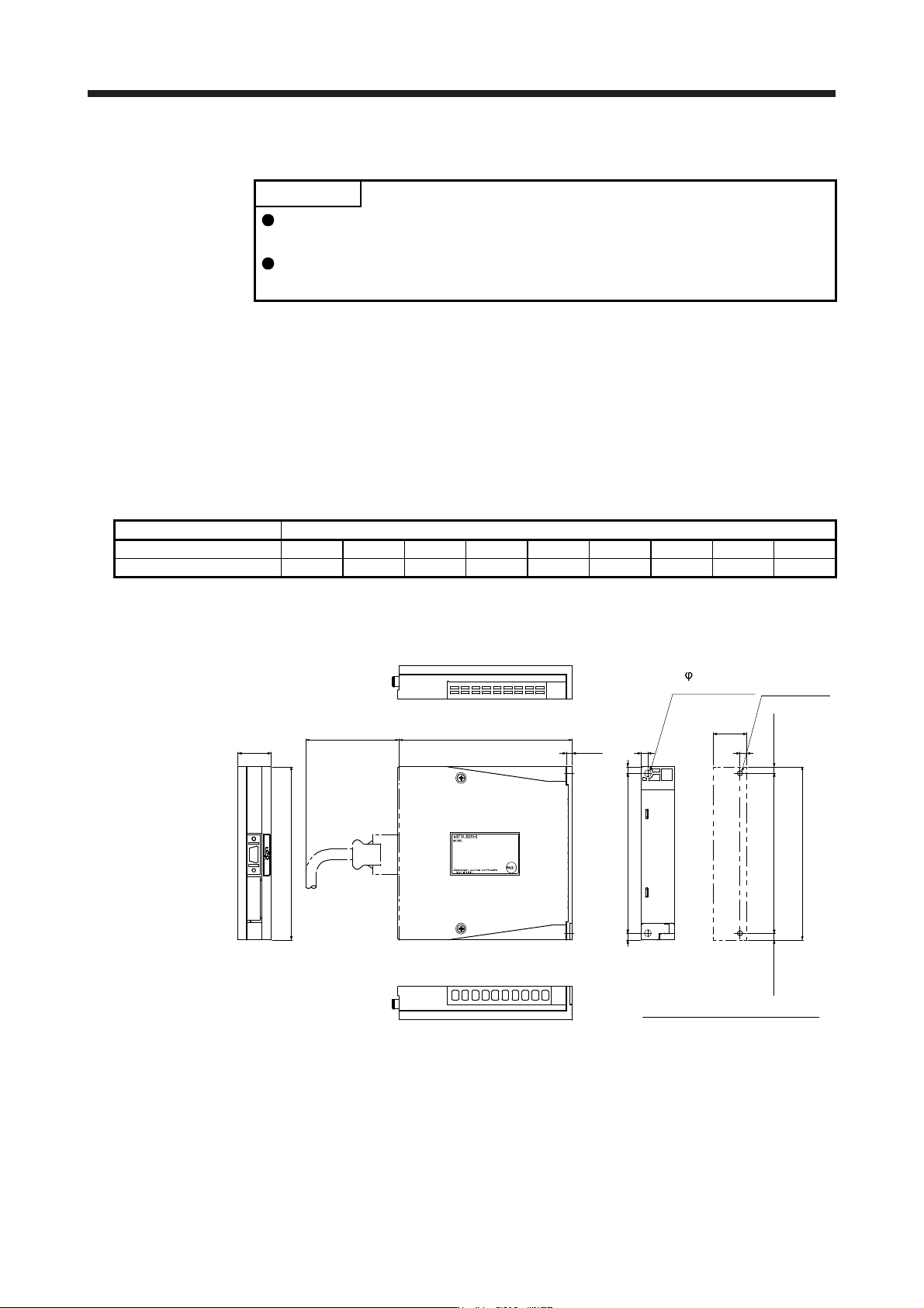
11.8.4 MR-BT6VCASE battery case
POINT
The battery unit consists of an MR-BT6VCASE battery case and five MR-
BAT6V1 batteries.
For the specifications and year and month of manufacture of MR-BAT6V1
battery, refer to section 11.8.5.
MR-BT6VCASE is a case used for connecting and mounting five MR-BAT6V1 batteries. A battery case does
not have any batteries. Please prepare MR-BAT6V1 batteries separately.
(1) The number of connected servo motors
One MR-BT6VCASE holds absolute position data up to eight axes servo motors. For direct drive motors,
up to four axes can be connected. Servo motors and direct drive motors in the incremental system are
included as the axis Nos. Linear servo motors are not counted as the axis Nos. Refer to the following
table for the number of connectable axes of each servo motor.
Servo motor Number of axes
Rotary servo motor 0 1 2 3 4 5 6 7 8
Direct drive motor 4 4 4 4 4 3 2 1 0
(2) Dimensions
[Unit: mm]
Mounting hole process drawing
2-M4 screw
Approx. 25
Approx. 130
Approx.5
Approx. 5
120 ± 0.5
5
5
5
130Approx. 70
25
130
4.6
1205
2- 5 mounting
hole
Mounting screw
Screw size: M4
[Mass: 0.18 k
g
]