sh030106u.pdf - 第393页
11. OPT ION S AND P ERI PHER AL EQU IPMENT 11 - 72 (1) Example of selec ting the w ire s izes Use the 600 V Gra de heat- resis tant polyv inyl c hloride i nsulat ed wire (HIV w ire) for wirin g. The fo llowing shows the …
11. OPTIONS AND PERIPHERAL EQUIPMENT
11 - 71
11.9 Selection example of wires
POINT
Refer to section 11.1.3 for SSCNET III cable.
To comply with the IEC/EN/UL/CSA standard, use the wires shown in app. 4 for
wiring. To comply with other standards, use a wire that is complied with each
standard.
For the selection example when the MR-J4-_B-RJ servo amplifier is used with
the DC power supply input, refer to app. 15.3.
Selection conditions of wire size are as follows.
Construction condition: Single wire set in midair
Wire length: 30 m or less
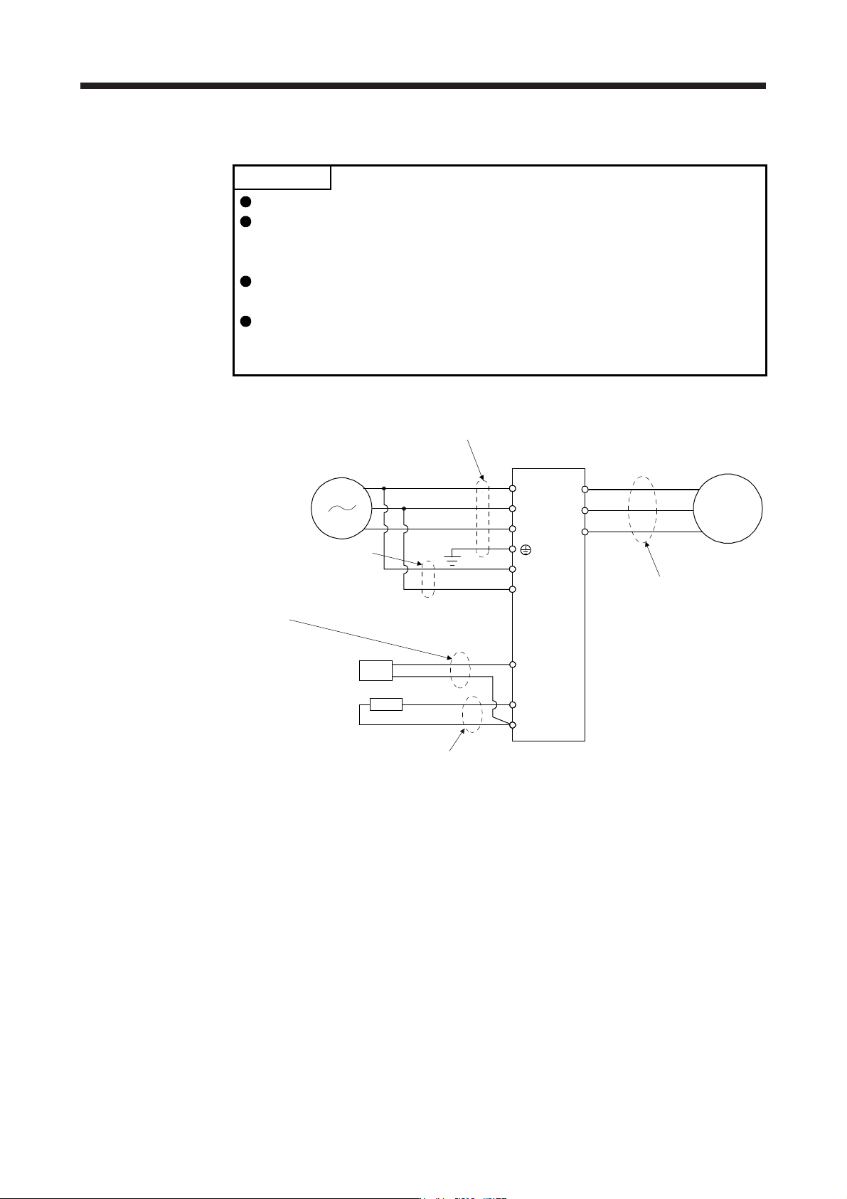
The following diagram shows the wires used for wiring. Use the wires given in this section or equivalent.
5) Power regeneration converter lead
Power regeneration
converter
N-
3) Regenerative option lead
Regenerative option
2) Control circuit power supply lead
C
P+
L1
L2
L3
L11
L21
1) Main circuit power supply lead
Power supply
Servo amplifier
U
V
W
M
4) Servo motor power supply lead
11. OPTIONS AND PERIPHERAL EQUIPMENT
11 - 72
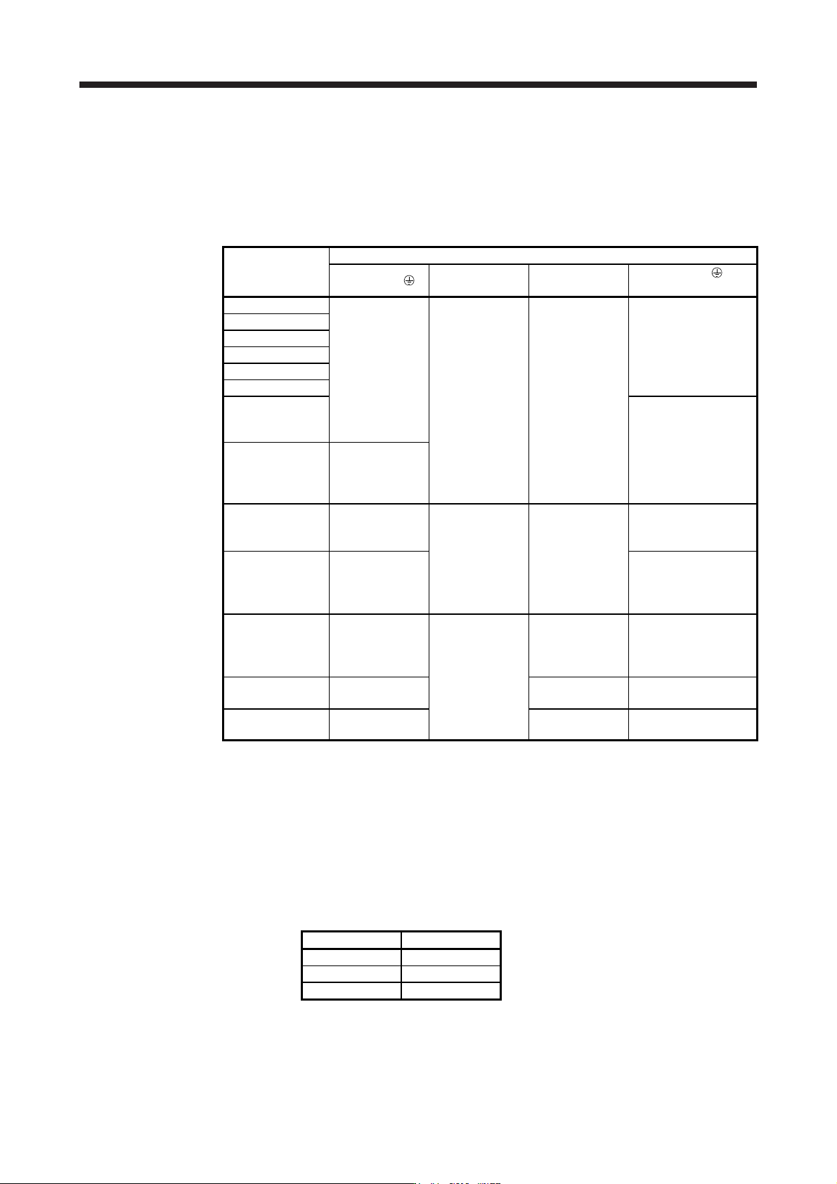
(1) Example of selecting the wire sizes
Use the 600 V Grade heat-resistant polyvinyl chloride insulated wire (HIV wire) for wiring. The following
shows the wire size selection example.
(a) 200 V class
Table 11.1 Wire size selection example (HIV wire)
Servo amplifier
Wire [mm
2
] (Note 1)
1) L1/L2/L3/ 2) L11/L21 3) P+/C
4) U/V/W/
(Note 3)
MR-J4-10B(-RJ)
2 (AWG 14)
1.25 to 2
(AWG 16 to 14)
(Note 4)
2 (AWG 14)
AWG 18 to 14
(Note 4)
MR-J4-20B(-RJ)
MR-J4-40B(-RJ)
MR-J4-60B(-RJ)
MR-J4-70B(-RJ)
MR-J4-100B(-RJ)
MR-J4-200B(-RJ)
(3-phase power
supply input)
AWG 16 to 10
MR-J4-200B(-RJ)
(1-phase power
supply input)
MR-J4-350B(-RJ)
3.5 (AWG 12)
MR-J4-500B(-RJ)
(Note 2)
5.5 (AWG 10): a
1.25 (AWG 16): a
2 (AWG 14): d
(Note 4)
2 (AWG 14): c
2 (AWG 14): c
3.5 (AWG 12): a
5.5 (AWG 10): a
MR-J4-700B(-RJ)
(Note 2)
8 (AWG 8): b
2 (AWG 14): c
3.5 (AWG 12): a
5.5 (AWG 10): a
8 (AWG 8): b
MR-J4-11KB(-RJ)
(Note 2)
14 (AWG 6): f
1.25 (AWG 16): c
2 (AWG 14): c
(Note 4)
3.5 (AWG 12): g
14 (AWG 6): f
5.5
(AWG 10): g (Note 5)
8 (AWG 8): k
MR-J4-15KB(-RJ)
(Note 2)
22 (AWG 4): h 5.5 (AWG 10): g
22 (AWG 4): h
8 (AWG 8): k (Note 5)
MR-J4-22KB(-RJ)
(Note 2)
38 (AWG 2): i 5.5 (AWG 10): j 38 (AWG 2): i
Note 1.
A
lphabets in the table indicate crimping tools. For crimp terminals and applicable tools, refer to
(
2
)
in this section.
2. To connect these models to a terminal block, be sure to use the screws that come with the
terminal block.
3. The wire size shows applicable size of the servo amplifier connector and terminal block. For wires
connectin
g
to the servo motor, refer to each servo amplifier instruction manual.
4. Be sure to use the size of 2 mm
2
when correspondin
g
to IEC/EN/UL/CS
A
standard.
5. This is for connectin
g
to the linear servo motor with natural coolin
g
method.
Use wires (5)) of the following sizes with the power regeneration converter (FR-RC).
Model Wire [mm
2
]
FR-RC-15K 14 (AWG 6)
FR-RC-30K 14 (AWG 6)
FR-RC-55K 22 (AWG 4)
11. OPTIONS AND PERIPHERAL EQUIPMENT
11 - 73
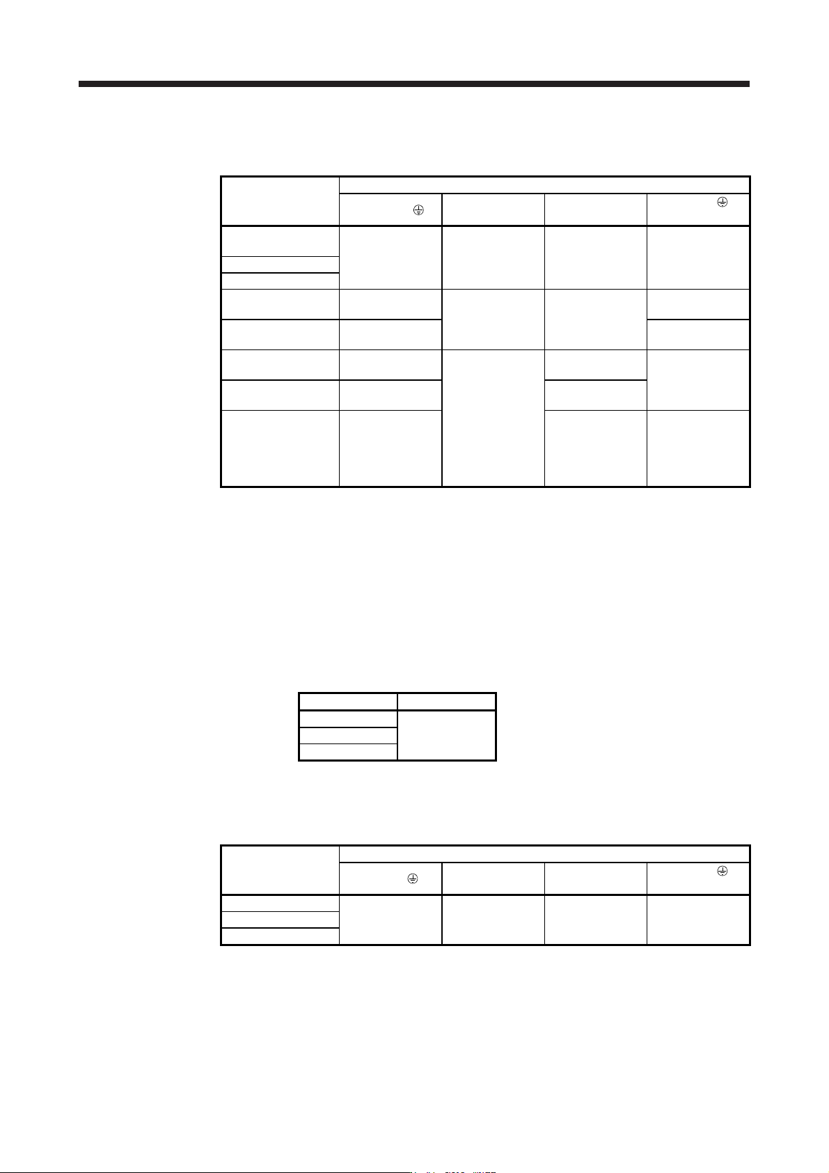
(b) 400 V class
Table 11.2 Wire size selection example (HIV wire)
Servo amplifier
Wires [mm
2
] (Note 1)
1) L1/L2/L3/
2) L11/L21 3) P+/C
4) U/V/W/
(Note 3)
MR-J4-60B4(-RJ)/
MR-J4-100B4(-RJ)
2 (AWG 14)
1.25 to 2
(AWG 16 to 14)
(Note 4)
2 (AWG 14) AWG 16 to 14
MR-J4-200B4(-RJ)
MR-J4-350B4(-RJ)
MR-J4-500B4(-RJ)
(Note 2)
2 (AWG 14): b
1.25 (AWG 16): a
2 (AWG 14): c
(Note 4)
2 (AWG 14): b
3.5 (AWG 12): a
MR-J4-700B4(-RJ)
(Note 2)
3.5 (AWG 12): a 5.5 (AWG 10): a
MR-J4-11KB4(-RJ)
(Note 2)
5.5 (AWG 10): d
1.25 (AWG 16): b
2 (AWG 14): b
(Note 4)
2 (AWG 14): f
8 (AWG 8): g
MR-J4-15KB4(-RJ)
(Note 2)
8 (AWG 8): g 3.5 (AWG 12): d
MR-J4-22KB4(-RJ)
(Note 2)
14 (AWG 6): i 3.5 (AWG 12): e
5.5 (AWG 10): e
(Note 5)
8 (AWG 8): h
(Note 6)
14 (AWG 6): i
Note 1.
A
lphabets in the table indicate crimping tools. For crimp terminals and applicable tools, refer to
(
2
)
in this section.
2. To connect these models to a terminal block, be sure to use the screws that come with the
terminal block.
3. The wire size shows applicable size of the servo amplifier connector and terminal block. For wires
connectin
g
to the servo motor, refer to each servo amplifier instruction manual.
4. Be sure to use the size of 2 mm
2
when correspondin
g
to IEC/EN/UL/CSA standard.
5. This is for connectin
g
to the linear servo motor with natural coolin
g
method.
6. This is for connectin
g
to the linear servo motor with liquid coolin
g
method.
Use wires (5)) of the following sizes with the power regeneration converter (FR-RC-H).
Model Wire [mm
2
]
FR-RC-H15K
14 (AWG 6)
FR-RC-H30K
FR-RC-H55K
(c) 100 V class
Table 11.3 Wire size selection example (HIV wire)
Servo amplifier
Wires [mm
2
]
1) L1/L2/ 2) L11/L21 3) P+/C
4) U/V/W/
(Note 1)
MR-J4-10B1(-RJ)
2 (AWG 14)
1.25 to 2
(AWG 16 to 14)
(Note 2)
2 (AWG 14)
AWG 18 to 14
(Note 2)
MR-J4-20B1(-RJ)
MR-J4-40B1(-RJ)
Note 1. The wire size shows applicable size of the servo amplifier connector and terminal block. For wires
connectin
g
to the servo motor, refer to each servo amplifier instruction manual.
2. Be sure to use the size of 2 mm
2
when correspondin
g
to IEC/EN/UL/CSA standard.