sh030106u.pdf - 第395页
11. OPT ION S AND P ERI PHER AL EQU IPMENT 11 - 74 (2) Selection example of crimp terminals (a) 200 V c lass Symbol Servo amplifier-side c rimp terminals (Note 2) Cri mp terminal Applic able tool Manufacturer Body Head D…
11. OPTIONS AND PERIPHERAL EQUIPMENT
11 - 73
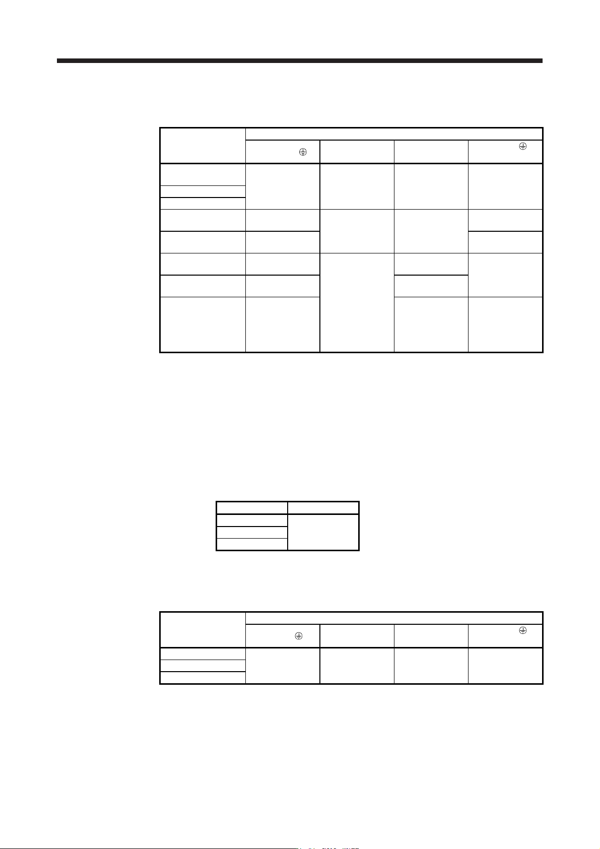
(b) 400 V class
Table 11.2 Wire size selection example (HIV wire)
Servo amplifier
Wires [mm
2
] (Note 1)
1) L1/L2/L3/
2) L11/L21 3) P+/C
4) U/V/W/
(Note 3)
MR-J4-60B4(-RJ)/
MR-J4-100B4(-RJ)
2 (AWG 14)
1.25 to 2
(AWG 16 to 14)
(Note 4)
2 (AWG 14) AWG 16 to 14
MR-J4-200B4(-RJ)
MR-J4-350B4(-RJ)
MR-J4-500B4(-RJ)
(Note 2)
2 (AWG 14): b
1.25 (AWG 16): a
2 (AWG 14): c
(Note 4)
2 (AWG 14): b
3.5 (AWG 12): a
MR-J4-700B4(-RJ)
(Note 2)
3.5 (AWG 12): a 5.5 (AWG 10): a
MR-J4-11KB4(-RJ)
(Note 2)
5.5 (AWG 10): d
1.25 (AWG 16): b
2 (AWG 14): b
(Note 4)
2 (AWG 14): f
8 (AWG 8): g
MR-J4-15KB4(-RJ)
(Note 2)
8 (AWG 8): g 3.5 (AWG 12): d
MR-J4-22KB4(-RJ)
(Note 2)
14 (AWG 6): i 3.5 (AWG 12): e
5.5 (AWG 10): e
(Note 5)
8 (AWG 8): h
(Note 6)
14 (AWG 6): i
Note 1.
A
lphabets in the table indicate crimping tools. For crimp terminals and applicable tools, refer to
(
2
)
in this section.
2. To connect these models to a terminal block, be sure to use the screws that come with the
terminal block.
3. The wire size shows applicable size of the servo amplifier connector and terminal block. For wires
connectin
g
to the servo motor, refer to each servo amplifier instruction manual.
4. Be sure to use the size of 2 mm
2
when correspondin
g
to IEC/EN/UL/CSA standard.
5. This is for connectin
g
to the linear servo motor with natural coolin
g
method.
6. This is for connectin
g
to the linear servo motor with liquid coolin
g
method.
Use wires (5)) of the following sizes with the power regeneration converter (FR-RC-H).
Model Wire [mm
2
]
FR-RC-H15K
14 (AWG 6)
FR-RC-H30K
FR-RC-H55K
(c) 100 V class
Table 11.3 Wire size selection example (HIV wire)
Servo amplifier
Wires [mm
2
]
1) L1/L2/ 2) L11/L21 3) P+/C
4) U/V/W/
(Note 1)
MR-J4-10B1(-RJ)
2 (AWG 14)
1.25 to 2
(AWG 16 to 14)
(Note 2)
2 (AWG 14)
AWG 18 to 14
(Note 2)
MR-J4-20B1(-RJ)
MR-J4-40B1(-RJ)
Note 1. The wire size shows applicable size of the servo amplifier connector and terminal block. For wires
connectin
g
to the servo motor, refer to each servo amplifier instruction manual.
2. Be sure to use the size of 2 mm
2
when correspondin
g
to IEC/EN/UL/CSA standard.
11. OPTIONS AND PERIPHERAL EQUIPMENT
11 - 74
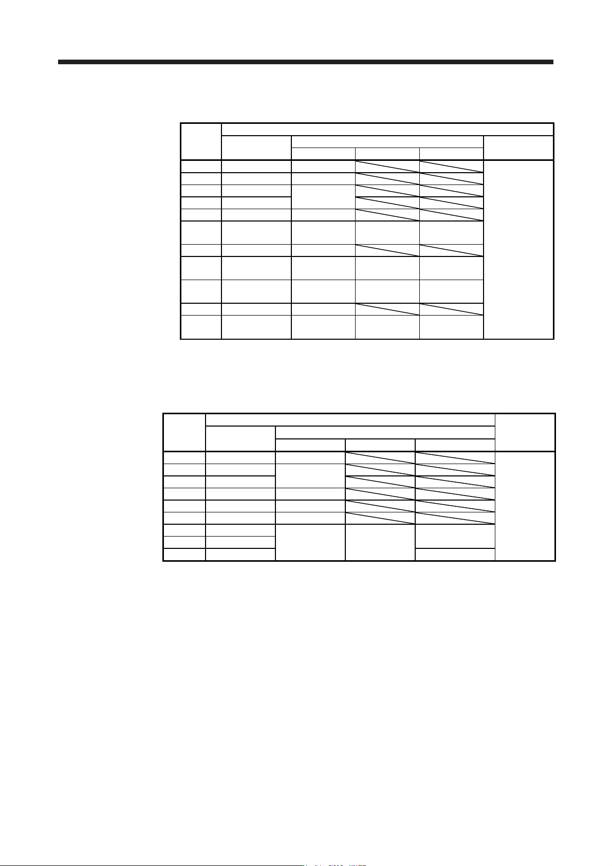
(2) Selection example of crimp terminals
(a) 200 V class
Symbol
Servo amplifier-side crimp terminals
(Note 2) Crimp
terminal
Applicable tool
Manufacturer
Body Head Dice
a FVD5.5-4 YNT-1210S
JST
b (Note 1) 8-4NS YHT-8S
c FVD2-4
YNT-1614
d FVD2-M3
e FVD1.25-M3 YNT-2216
f FVD14-6 YF-1 YNE-38
DH-122
DH-112
g FVD5.5-6 YNT-1210S
h FVD22-6 YF-1 YNE-38
DH-123
DH-113
i FVD38-8 YF-1 YNE-38
DH-124
DH-114
j FVD5.5-8 YNT-1210S
k FVD8-6 YF-1/E-4 YNE-38
DH-121
DH-111
Note 1. Coat the crimpin
g
part with an insulation tube.
2. Some crimp terminals may not be mounted depending on the size. Make sure to use the
recommended ones or equivalent ones.
(b) 400 V class
Symbol
Servo amplifier-side crimp terminals
Manufacturer
Crimp terminal
(Note)
Applicable tool
Body Head Dice
a FVD5.5-4 YNT-1210S
JST
b FVD2-4
YNT-1614
c FVD2-M3
d FVD5.5-6 YNT-1210S
e FVD5.5-8 YNT-1210S
f FVD2-6 YNT-1614
g FVD8-6
YF-1 YNE-38
DH-121/DH-111
h FVD8-8
i FVD14-8 DH-122/DH-112
Note. Some crimp terminals may not be mounted depending on the size. Make sure to use the
recommended ones or equivalent ones.
11. OPTIONS AND PERIPHERAL EQUIPMENT
11 - 75
11.10 Molded-case circuit breakers, fuses, magnetic contactors
CAUTION
To prevent the servo amplifier from smoke and a fire, select a molded-case circuit
breaker which shuts off with high speed.
Always use one molded-case circuit breaker and one magnetic contactor with one
servo amplifier.
POINT
For the selection when the MR-J4-_B-RJ servo amplifier is used with the DC
power supply input, refer to app. 15.4.