sh030106u.pdf - 第398页
11. OPT ION S AND P ERI PHER AL EQU IPMENT 11 - 77 The Type E Comb inatio n motor c ontroll er can a lso be used ins tea d of a mold ed-c ase circ uit break er. Servo amplifi er Rated input voltage A C [V] Input phase Ty…
11. OPTIONS AND PERIPHERAL EQUIPMENT
11 - 76
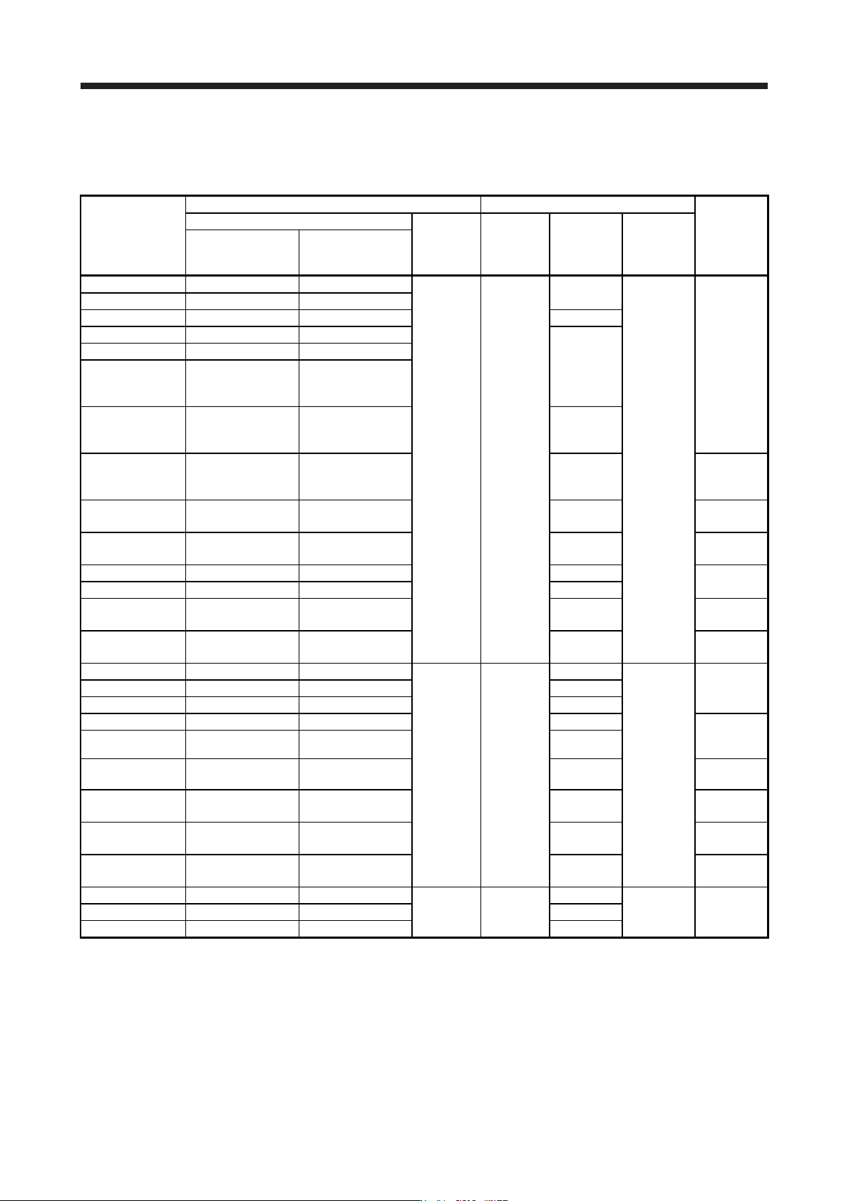
(1) For main circuit power supply
When using a fuse instead of the molded-case circuit breaker, use the one having the specifications
given in this section.
Servo amplifier
Molded-case circuit breaker (Note 1) Fuse
Magnetic
contactor
(Note 2)
Frame, rated current
Voltage AC
[V]
Class Current [A]
Voltage AC
[V]
Power factor
improving reactor is
not used
Power factor
improving reactor is
used
MR-J4-10B(-RJ) 30 A frame 5 A 30 A frame 5 A
240 T
10
300
S-N10
S-T10
MR-J4-20B(-RJ) 30 A frame 5 A 30 A frame 5 A
MR-J4-40B(-RJ) 30 A frame 10 A 30 A frame 5 A 15
MR-J4-60B(-RJ) 30 A frame 15 A 30 A frame 10 A
20
MR-J4-70B(-RJ) 30 A frame 15 A 30 A frame 10 A
MR-J4-100B(-RJ)
(3-phase power
supply input)
30 A frame 15 A 30 A frame 10 A
MR-J4-100B(-RJ)
(1-phase power
supply input)
30 A frame 15 A 30 A frame 15 A 30
MR-J4-200B(-RJ) 30 A frame 20 A 30 A frame 20 A 40
S-N20
(Note 3)
S-T21
MR-J4-350B(-RJ) 30 A frame 30 A 30 A frame 30 A 70
S-N20
S-T21
MR-J4-500B(-RJ) 50 A frame 50 A 50 A frame 50 A 125
S-N35
S-T35
MR-J4-700B(-RJ) 100 A frame 75 A 60 A frame 60 A 150
S-N50
S-T50
MR-J4-11KB(-RJ) 100 A frame 100 A 100 A frame 100 A 200
MR-J4-15KB(-RJ) 125 A frame 125 A 125 A frame 125 A 250
S-N65
S-T65
MR-J4-22KB(-RJ) 225 A frame 175 A 225 A frame 175 A 350
S-N95
S-T100
MR-J4-60B4(-RJ) 30 A frame 5 A 30 A frame 5 A
480 T
10
600
S-N10
S-T10
MR-J4-100B4(-RJ) 30 A frame 10 A 30 A frame 5 A 15
MR-J4-200B4(-RJ) 30 A frame 15 A 30 A frame 10 A 25
MR-J4-350B4(-RJ) 30 A frame 20 A 30 A frame 15 A 35
S-N20
(Note 3)
S-T21
MR-J4-500B4(-RJ) 30 A frame 20 A 30 A frame 20 A 50
MR-J4-700B4(-RJ) 30 A frame 30 A 30 A frame 30 A 65
S-N20
S-T21
MR-J4-11KB4(-RJ) 50 A frame 50 A 50 A frame 50 A 100
S-N25
S-T35
MR-J4-15KB4(-RJ) 60 A frame 60 A 60 A frame 60 A 150
S-N35
S-T35
MR-J4-22KB4(-RJ) 100 A frame 100 A 100 A frame 100 A 175
S-N50
S-T50
MR-J4-10B1(-RJ) 30 A frame 5 A 30 A frame 5 A
240 T
10
300
S-N10
S-T10
MR-J4-20B1(-RJ) 30 A frame 10 A 30 A frame 10 A 15
MR-J4-40B1(-RJ) 30 A frame 15 A 30 A frame 10 A 20
Note 1. When havin
g
the servo amplifier compl
y
with the IEC/EN/UL/CSA standard, refer to app. 4.
2. Use a magnetic contactor with an operation delay time (interval between current being applied to the coil until closure of
contacts
)
of 80 ms or less.
3. S-N18 can be used when auxiliar
y
contact is not required.
11. OPTIONS AND PERIPHERAL EQUIPMENT
11 - 77
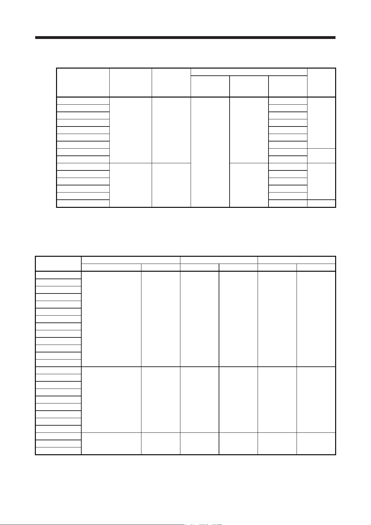
The Type E Combination motor controller can also be used instead of a molded-case circuit breaker.
Servo amplifier
Rated input
voltage AC [V]
Input phase
Type E Combination motor controller
SCCR
[kA]
Model
Rated
voltage
AC [V]
Rated current
[A]
(Heater design)
MR-J4-10B(-RJ)
200 to 240 3-phase
MMP-T32
240
1.6
50
MR-J4-20B(-RJ) 2.5
MR-J4-40B(-RJ) 4
MR-J4-60B(-RJ) 6.3
MR-J4-70B(-RJ) 6.3
MR-J4-100B(-RJ) 8
MR-J4-200B(-RJ) 18
MR-J4-350B(-RJ) 25
25
MR-J4-500B(-RJ) 32
MR-J4-60B4(-RJ)
380 to 480 3-phase 480Y/277
2.5
50
MR-J4-100B4(-RJ) 4
MR-J4-200B4(-RJ) 8
MR-J4-350B4(-RJ) 13
MR-J4-500B4(-RJ) 18
MR-J4-700B4(-RJ) 25 25
(2) For control circuit power supply
When the wiring for the control circuit power supply (L11/L21) is thinner than that for the main circuit
power supply (L1/L2/L3), install an overcurrent protection device (molded-case circuit breaker or fuse) to
protect the branch circuit.
Servo amplifier
Molded-case circuit breaker (Note) Fuse (Class T) Fuse (Class K5)
Frame, rated current Voltage AC [V] Current [A] Voltage AC [V] Current [A] Voltage AC [V]
MR-J4-10B(-RJ)
MR-J4-20B(-RJ)
MR-J4-40B(-RJ)
MR-J4-60B(-RJ)
MR-J4-70B(-RJ)
MR-J4-100B(-RJ)
MR-J4-200B(-RJ) 30 A frame 5 A 240 1 300 1 250
MR-J4-350B(-RJ)
MR-J4-500B(-RJ)
MR-J4-700B(-RJ)
MR-J4-11KB(-RJ)
MR-J4-15KB(-RJ)
MR-J4-22KB(-RJ)
MR-J4-60B4(-RJ)
MR-J4-100B4(-RJ)
MR-J4-200B4(-RJ)
MR-J4-350B4(-RJ)
MR-J4-500B4(-RJ) 30 A frame 5 A 480 1 600 1 600
MR-J4-700B4(-RJ)
MR-J4-11KB4(-RJ)
MR-J4-15KB4(-RJ)
MR-J4-22KB4(-RJ)
MR-J4-10B1(-RJ)
MR-J4-20B1(-RJ) 30 A frame 5 A 240 1 300 1 250
MR-J4-40B1(-RJ)
Note. When havin
g
the servo amplifier compl
y
with the IEC/EN/UL/CSA standard, refer to app. 4.
11. OPTIONS AND PERIPHERAL EQUIPMENT
11 - 78
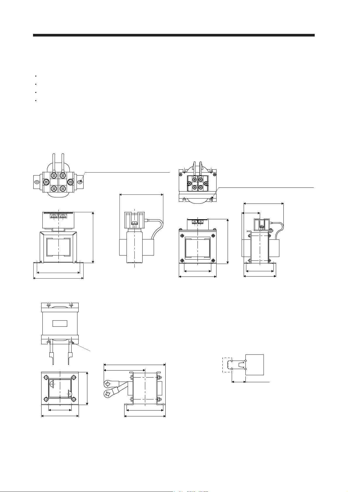
11.11 Power factor improving DC reactors
The following shows the advantages of using power factor improving DC reactor.
It improves the power factor by increasing the form factor of the servo amplifier's input current.
It decreases the power supply capacity.
The input power factor is improved to about 85%.
As compared to the power factor improving AC reactor (FR-HAL-(H)), it decreases the loss.
When connecting the power factor improving DC reactor to the servo amplifier, always disconnect P3 and
P4. If it remains connected, the effect of the power factor improving DC reactor is not produced.
When used, the power factor improving DC reactor generates heat. To release heat, therefore, leave a 10
cm or more clearance at each of the top and bottom, and a 5 cm or more clearance on each side.
(1) 200 V class
2-d mounting hole
(Varnish is removed from right mounting
hole (face and back side).) (Note 1)
D or less
W ± 2
W1
H
PP1
Fig. 11.1
4-d mounting hole
(Varnish is removed from front right mounting
hole (face and back side).) (Note 1)
D or less
W ± 2
W1
H
D1
D3
D2
PP1
Fig. 11.2
D or less
D3 or less
W ± 2
W1
D1 ± 2
D2
H ± 2
4-d mounting hole (Note 1)
P1
P
Fig. 11.3
(Note 2)
Servo amplifier
P3
P4
FR-HEL
5 m or less
P1
P
Note 1. Use this for
g
roundin
g
.
2. When usin
g
the power factor improvin
g
DC reactor, remove the short bar across P3 and P4.