sh030106u.pdf - 第403页
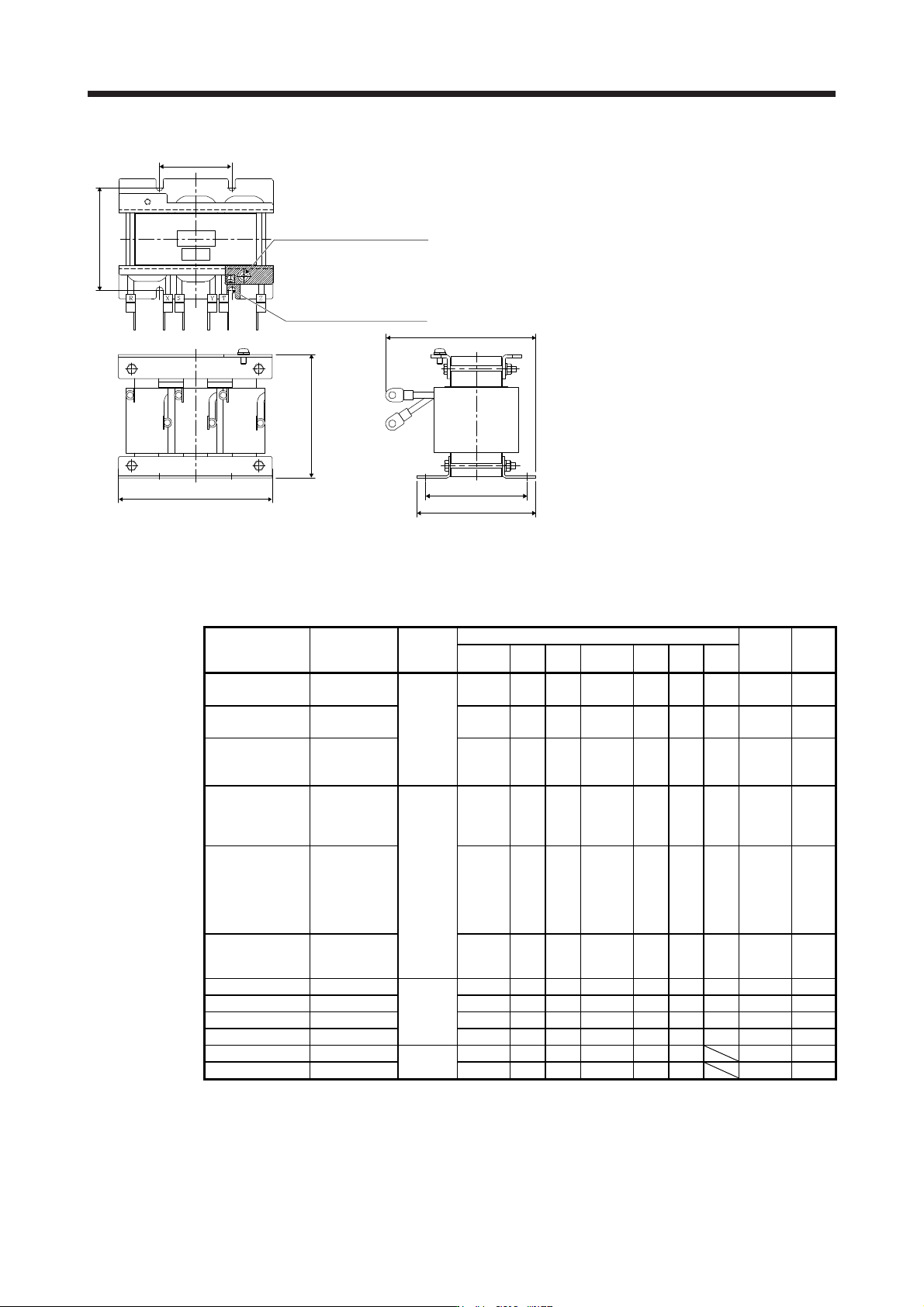
11. OPTIONS AND PERIPHERAL EQUIPMENT 11 - 82 W H MAX D D1 D2 W1 D2 Earth (ground) terminal Wire the earthing (grounding) cable to t he ear th ( ground) ter minal Installation hole for 4-M6 (near right side, varnish remov…
11. OPTIONS AND PERIPHERAL EQUIPMENT
11 - 81
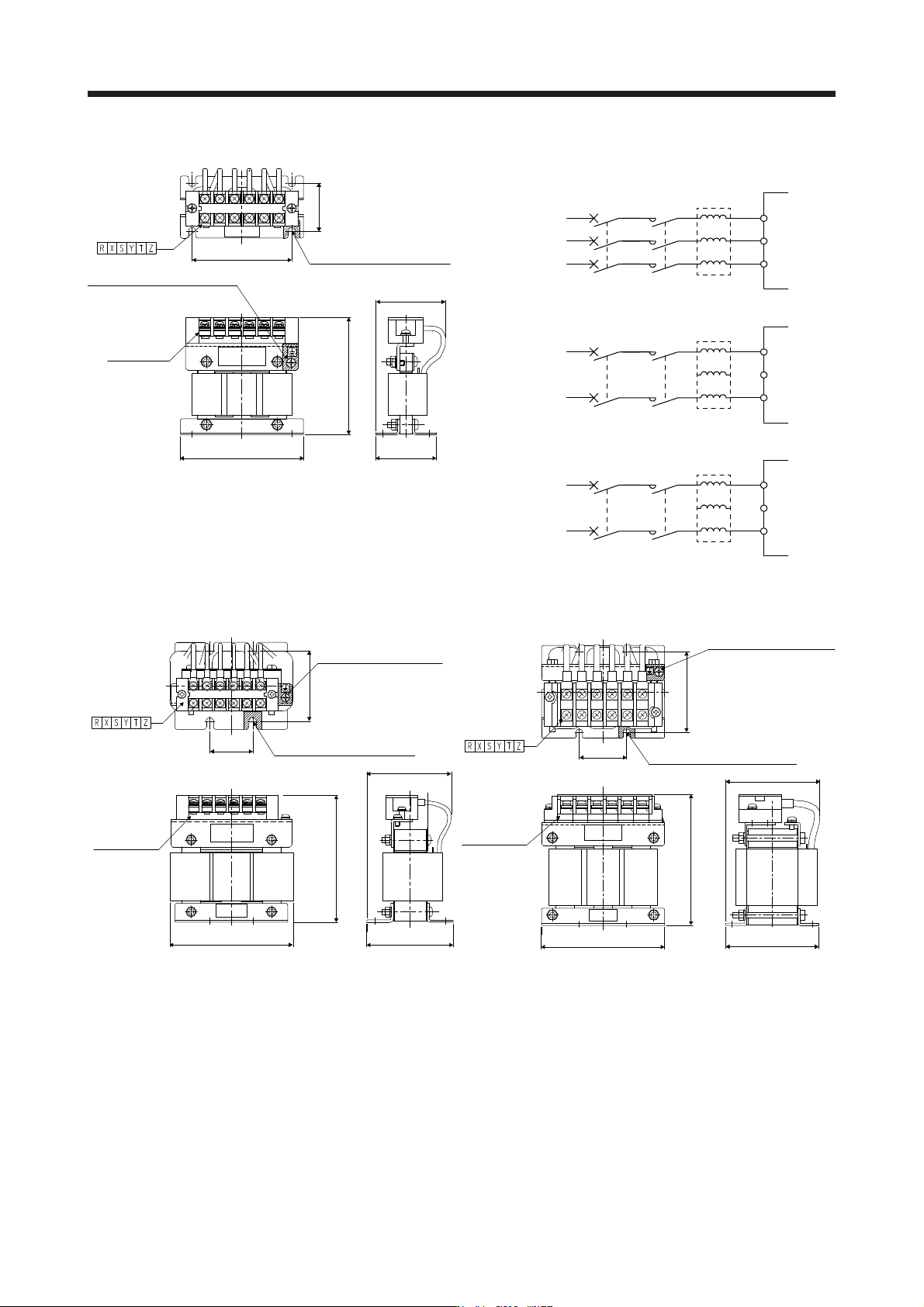
(1) 200 V class/100 V class
D2
W1
W
H
D1
D
Terminal layout
Installation hole for 4-d
(near right side, varnish removed)
Earth (ground) terminal
W
ire the earthing (grounding) cable
t
o the earth (ground) terminal
Terminal block
(with cover)
Fig. 11.7
Y
Z
S
T
Y
Z
S
T
MCMCCB
MCMCCB
FR-HAL
XR
L1
L2
L3
FR-HAL
XR
L1
L2
L3
Y
Z
S
T
MCMCCB
FR-HAL
XR
L1
L2
Servo amplifier
3-phase 200 V class
3-phase
2
00 V AC to
2
40 V AC
Servo amplifier
1-phase 200 V class
(Note)
1-phase
2
00 V AC to
2
40 V AC
Servo amplifier
1-phase 100 V class
1-phase
100 V AC to
120 V AC
Unassigned
Note. For 1-phase 200 V AC to 240 V AC, connect the power
supply to L1 and L3. Leave L2 open.
D2
W1
W
H
D1
D
Terminal layout
Installation hole for 4-d
(near right side, varnish removed)
Earth (ground) terminal
Wire the earthing (grounding)
cable to the earth (ground)
terminal
Terminal block
(with cover)
Fig. 11.8
W1
D2
W
H
D1
MAX D
Terminal layout
Earth (ground) terminal
Wire the earthing (grounding)
cable to the earth (ground)
terminal
Terminal block
(with cover)
Installation hole for 4-d
(near right side, varnish removed)
Fig. 11.9
11. OPTIONS AND PERIPHERAL EQUIPMENT
11 - 82
W
H
MAX D
D1
D2
W1
D2
Earth (ground) terminal
Wire the earthing (grounding) cable
to the earth (ground) terminal
Installation hole for 4-M6
(near right side, varnish removed)
Fig. 11.10
Servo amplifier
Power factor
improving AC
reactor
Dimensions
Dimensions [mm]
Terminal
size
Mass
[kg]
W W1 H D (Note) D1 D2 d
MR-J4-10B(-RJ)
MR-J4-20B(-RJ)
FR-HAL-0.4K
Fig. 11.7
104 84 99 72 51 40 M5 M4 0.6
MR-J4-40B(-RJ)
MR-J4-10B1(-RJ)
FR-HAL-0.75K 104 84 99 74 56 44 M5 M4 0.8
MR-J4-60B(-RJ)
MR-J4-70B(-RJ)
MR-J4-20B1(-RJ)
FR-HAL-1.5K 104 84 99 77 61 50 M5 M4 1.1
MR-J4-100B(-RJ)
(3-phase power
supply input)
MR-J4-40B1(-RJ)
FR-HAL-2.2K
Fig. 11.8
115 40 115 77 71 57 M6 M4 1.5
MR-J4-100B(-RJ)
(1-phase power
supply input)
MR-J4-200B(-RJ)
(3-phase power
supply input)
FR-HAL-3.7K 115 40 115 83 81 67 M6 M4 2.2
MR-J4-200B(-RJ)
(1-phase power
supply input)
FR-HAL-5.5K 115 40 115 83 81 67 M6 M4 2.3
MR-J4-350B(-RJ) FR-HAL-7.5K
Fig. 11.9
130 50 135 100 98 86 M6 M5 4.2
MR-J4-500B(-RJ) FR-HAL-11K 160 75 164 111 109 92 M6 M6 5.2
MR-J4-700B(-RJ) FR-HAL-15K 160 75 167 126 124 107 M6 M6 7.0
MR-J4-11KB(-RJ) FR-HAL-15K 160 75 167 126 124 107 M6 M6 7.0
MR-J4-15KB(-RJ) FR-HAL-22K
Fig. 11.10
185 75 150 158 100 87 M6 9.0
MR-J4-22KB(-RJ) FR-HAL-30K 185 75 150 168 100 87 M6 9.7
Note. Maximum dimensions The dimension varies depending on the input/output lines.
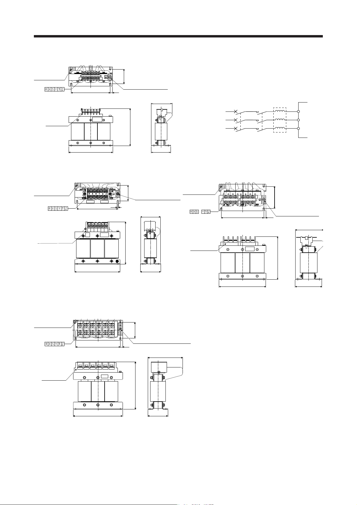
11. OPTIONS AND PERIPHERAL EQUIPMENT
11 - 83
(2) 400 V class
WD1
D
H
W2
W1
D2
Installation hole for
4-d varnish removed
(front, rear)
Terminal layout
Earth (ground) terminal
Wire the earthing (grounding)
cable to the earth (ground)
terminal
Terminal block
(with cover)
Fig. 11.11
Y
Z
S
T
MCMCCB
FR-HAL-H
XR
L1
L2
L3
Servo amplifie
r
3-phase 400 V calss
3-phase
380 V AC to
4
80 V AC
W
H
D1
D
W2
W1
D2
Earth (ground) terminal
Wire the earthing (grounding)
cable to the earth (ground)
terminal
Terminal block(with cover)
Installation hole for 4-d
(varnish removed
(front, rear))
Terminal layout
D1
D
W
H
D2
W2W1
Earth (ground) terminal
Wire the earthing (grounding)
cable to the earth (ground)
terminal
Installation hole for 4-d
Varnish removed
(front, rear)
Terminal layout
Terminal block (2)
(with cover)
Fig. 11.12 Fig. 11.13
D1
MAX D
W
HD2
W2W1
Terminal layout
Terminal block
(with cover)
Earth (ground) terminal
Wire the earthing (grounding) cable
to the earth (ground) terminal
Installation hole for 4-d
(varnish removed
(front, rear))
Fig. 11.14