sh030106u.pdf - 第409页
11. OPT I ONS AND PER IPH ERA L EQU IPM ENT 11 - 8 8 (c) Cable clamp f itting AER SBAN-_SET Generally , connec ting t he ground ing of t he shiel ded wir e to the SD ter minal of t he connec tor provides a suffic ient ef…
11. OPTIONS AND PERIPHERAL EQUIPMENT
11 - 87
(2) Nois
e reduction techniques
(a) Data line filter (recommended)
Noise can be prevented by installing a data line filter onto the encoder cable, etc.
For example, ZCAT3035-1330 by TDK, ESD-SR-250 by TOKIN, GRFC-13 by Kitagawa Industries,
and E04SRM563218 by SEIWA ELECTRIC are available as data line filte
rs.
As a reference example, the impedance specifications of the ZCAT3035-1330 (TDK) are indicated
below. These impedances are reference values and not guaranteed values.
Impedance [Ω]
[Unit: mm]
Outline drawing (ZCAT3035-1330)
Loop for fixing the
cable band
Lot number
Product name
TDK
39 ± 1
34 ± 1
φ13 ± 1
φ30 ± 1
10 MHz to 100 MHz 100 MHz to 500 MHz
80 150
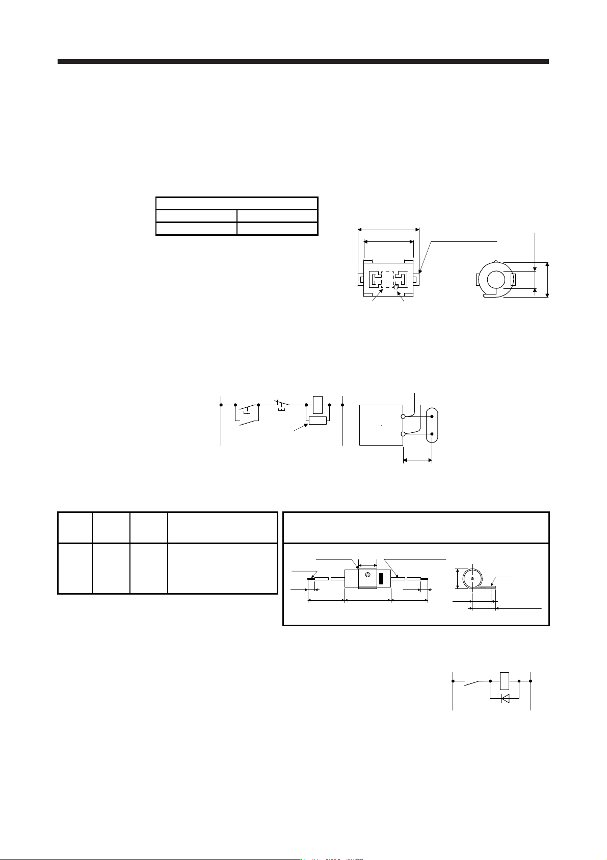
(b) Surge killer (recommended)
Use of a surge killer is recommended for AC relay, magnetic contactor or the like near the servo
amplifier. Use the following surge killer or equivalent.
MC
SK
Surge kille
r
Relay
Surge killer
MC
ON
OFF
This distance should be short
(within 20 cm).
(Ex
.) CR-50500 Okaya Electric Industries)
Rated
voltage
AC [V]
C
[µF ± 20%]
R
[Ω ± 30%]
Test voltage Dimensions [Unit: mm]
250 0.5 50 (1/2 W)
Between terminals: 625 V AC,
50 Hz/60 Hz 60 s
Between terminal and case:
2000 V AC
50/60 Hz 60 s
6 ± 1
300 min. 300 min.
Soldered
Band (clear) AWG 18 Twisted wire
15 ± 1
48 ± 1.5
CR-50500
6 ± 1
16 ± 1
(18.5 + 5) max.
φ3.6
φ(18.5 + 2) ± 1
Note that a d
iode should be installed to a DC relay or the like.
Maximum voltage: Not less than four times the drive voltage of the relay or
the like.
Maximum current: Not less than twice the drive current of the relay or the
like.
-+
Diode
RA
11. OPTIONS AND PERIPHERAL EQUIPMENT
11 - 88
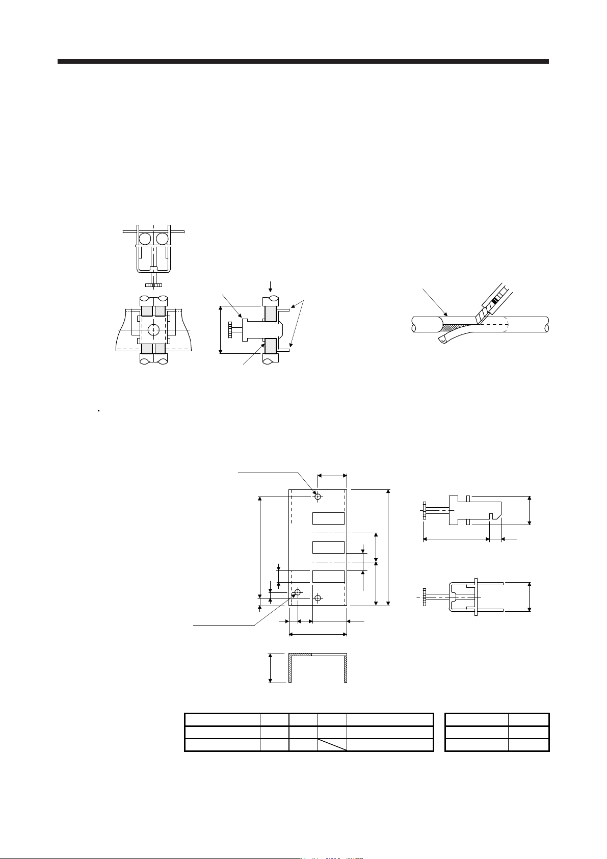
(c)
Cable clamp fitting AERSBAN-_SET
Generally, connecting the grounding of the shielded wire to the SD terminal of the connector
provides a sufficient effect. However, the effect can be increased when the shielded wire is
connected directly to the grounding plate as shown below.
Install the grounding plate near the servo amplifier for the encoder cable. Peel part of the cabl
e
sheath to expose the external conductor, and press that part against the grounding plate with the
cable clamp. If the cable is thin, clamp several cables in a bunch.
The cable clamp comes as a set with the grounding plate.
[Unit: mm]
Cable clamp
(A, B)
Cable
Earth plate
External conductor
Clamp section diagram
40
Strip the cable sheath of
the clamped area.
cutter
cable
Dimensions
[Unit: mm]
Earth plate
(Note) M4 screw
11
3
6
C
A
622
17.5
35
35
7
24
0
-0.2
B ± 0.3
2-φ5 hole
installation hole
[Unit: mm]
Clamp section diagram
L or less 10
30
24
+ 0.3
0
Note. Screw hole for
g
roundin
g
. Connect it to the
g
roundin
g
plate of the cabinet.
Model A B C Accessory fittings Clamp fitting L
AERSBAN-DSET 100 86 30 Clamp A: 2pcs. A 70
AERSBAN-ESET 70 56 Clamp B: 1pc. B 45
11. OPTIONS AND PERIPHERAL EQUIPMENT
11 - 89
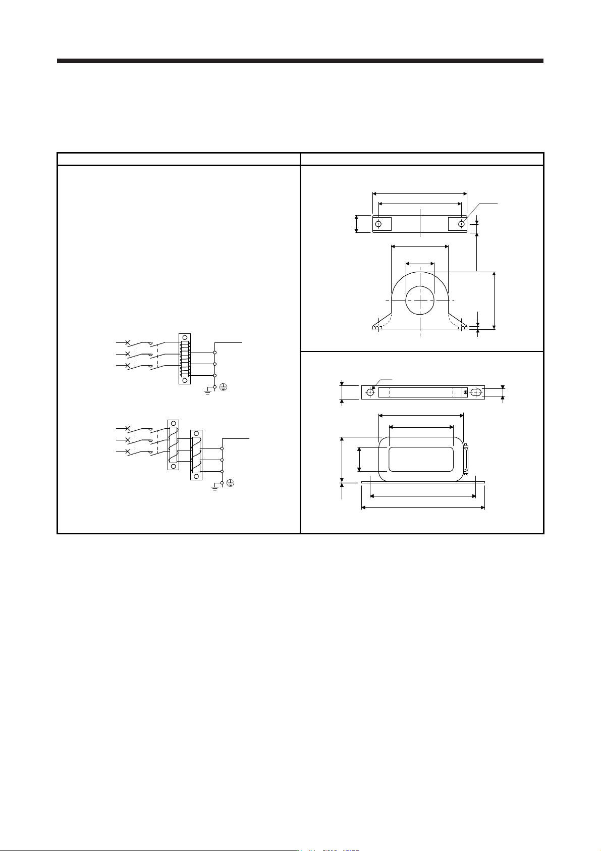
(d) Li
ne noise filter (FR-BSF01/FR-BLF)
This filter is effective in suppressing noises radiated from the power supply side and output sid
e of
the servo amplifier and also in suppressing high-frequency leakage current (0-phase current). It
especially affects the noises between 0.5 MHz and 5 MHz band.
Connection diagram Dimensions [Unit: mm]
The line noise filters can be mounted on lines of the main power
supply (L1/L2/L3) and of the servo motor power (U/V/W). Pass
each of the wires through the line noise filter an equal number of
times in the same direction. For wires of the main power supply,
the effect of the filter rises as the number of passes increases, but
generally four passes would be appropriate. For the servo motor
power lines, passes must be four times or less. Do not pass the
grounding wire through the filter. Otherwise, the effect of the filter
will drop.
Wind the wires by passing through the filter to satisfy the required
number of passes as shown in Example 1. If the wires are too
thick to wind, use two or more filters to have the required number
of passes as shown in Example 2.
Place the line noise filters as close to the servo amplifier as
possible for their best performance.
MCMCCB
Example 1
Power
supply
Power
supply
Servo amplifier
Line noise
filter
L1
L2
L3
(Number of passes: 4)
MCMCCB
Line noise
filter
Example 2
Servo amplifie
r
L1
L2
L3
Two filters are used
(Total number of passes: 4)
FR-BSF01 (for wire size 3.5 mm
2
(AWG 12) or less)
φ33
4.5
Approx. 110
95 ± 0.5
Approx. 22.5
Approx. 65
Approx. 65
2-φ
5
11.25 ± 0.5
FR-BLF (for wire size 5.5 mm
2
(AWG 10) or more)
130
85
35
31.5
7
80
2.3
160
180
φ7