sh030106u.pdf - 第41页
1. FUNCTI ONS AND CONF IGURATION 1 - 24 1.7 Struc ture 1.7.1 Parts ide ntificat ion (1) 200 V clas s (a) MR-J4-200B(-RJ) or l ess The diagra m is f or MR-J4- 10B-RJ . (1) (3) (2) Inside of the display cover (5) (18) (13)…
1. FUNCTIONS AND CONFIGURATION
1 - 23
1.6 Model designation
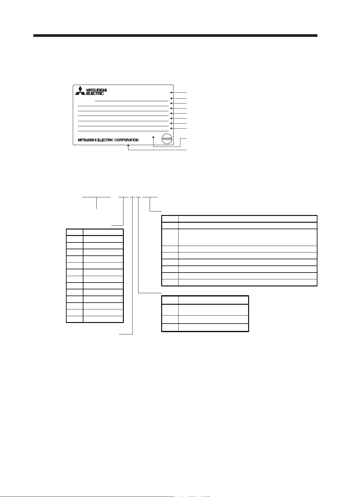
(1) Rating plate
The following shows an example of rating plate for explanation of each item.
Country of origin
Model
Capacity
Applicable power supply
Rated output current
Standard, Manual number
Ambient temperature
IP rating
KC number, The year and month of manufacture manufacture
Serial number
TOKYO 100-8310, JAPAN MADE IN JAPAN
IP20
KCC-REI-MEK-TC300A624G51
Max. Surrounding Air Temp.: 55°C
POWER :100W
MR-J4-10B
AC SERVO
SER.A45001001
OUTPUT: 3PH170V 0-360Hz 1.1A
MAN.: IB(NA)0300175
INPUT : 3AC/AC200-240V 0.9A/1.5A 50/60Hz
STD.: IEC/EN 61800-5-1
DATE:2014-05
MODEL
(2) Model
The following describes what each block of a model name indicates. Not all combinations of the symbols
are available.
MR - J 4 - 6 0 B 4 - RJ
Series
Rated output
SSCNETIII/H interface
Special specifications
Symbol Rated output [kW]
10 0.1
20 0.2
40 0.4
Symbol Special specifications
None Standard
MR-J4-_B_ without regenerative resistor (Note 1)
MR-J4-_B_-RJ without regenerative resistor (Note 1)
MR-J4-_B_ with a special coating specification (3C2) (Note 3)
MR-J4-_B_-RJ with a special coating specification (3C2) (Note 3)
-RJ
Fully closed loop control four-wire type/load-side encoder
A/B/Z-phase input compatible/Compatible with MR-D30
functional safety unit
60 0.6
70 0.75
100 1
200 2
350 3.5
500 5
700 7
11K 11
15K 15
22K 22
-PX
-RZ
-EB
-KS
Power supply
Symbol Power supply
None
3-phase or 1-phase
200 V AC to 240 V AC
4
3-phase 380 V AC to 480 V AC
1
1-phase 100 V AC to 120 V AC
MR-J4-_B_ without a dynamic brake (Note 2)
MR-J4-_B_-RJ without a dynamic brake (Note 2)
-ED
-RU
Note 1. Indicates a servo amplifier of 11 kW to 22 kW that does not use a regenerative resistor as standard accessory.
Refer to app. 11.2 for details.
2. D
y
namic brake which is built in 7
k
W or smaller servo amplifiers is removed. Refer to app. 11.1 for details.
3. Type with a specially-coated servo amplifier board (IEC 60721-3-3:1994 Class 3C2). Refer to app. 11.3 for
details.
1. FUNCTIONS AND CONFIGURATION
1 - 24
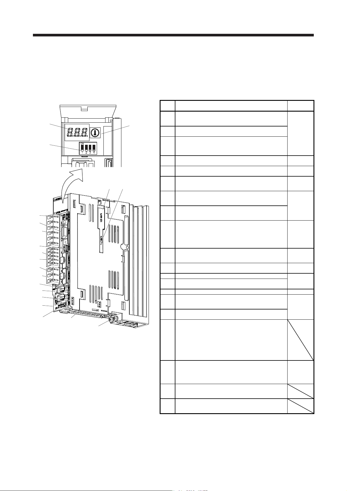
1.7 Structure
1.7.1 Parts identification
(1) 200 V class
(a) MR-J4-200B(-RJ) or less
The diagram is for MR-J4-10B-RJ.
(1)
(3)
(2)
Inside of the display cover
(5)
(18)
(13)
(10)
(17)
(9)
(6)
(7)
(11)
Bottom
(16)
(15)
(8)
(4)
(14)
Side
(12)
(19)(20)
No. Name/Application
Detailed
explanation
(1)
Display
The 3-digit, 7-segment LED shows the servo status
and the alarm number.
Section 4.3
(2)
Axis selection rotary switch (SW1)
Used to set the axis No. of servo amplifier.
(3)
Control axis setting switch (SW2)
The test operation switch, the disabling control axis
switch, and the auxiliary axis number setting switch
are available.
(4)
USB communication connector (CN5)
Connect with the personal computer.
Section
11.7
(5)
I/O signal connector (CN3)
Used to connect digital I/O signals.
Section 3.2
Section 3.4
(6)
STO input signal connector (CN8)
Used to connect MR-J3-D05 safety logic unit and
external safety relay.
Chapter 13
App. 5
(7)
SSCNET III cable connector (CN1A)
Used to connect the servo system controller or the
previous axis servo amplifier.
Section 3.2
Section 3.4
(8)
SSCNET III cable connector (CN1B)
Used to connect the next axis servo amplifier. For
the final axis, put a cap.
(9)
(Note
2)
Encoder connector (CN2)
Used to connect the servo motor encoder.
Used to connect the servo motor encoder or
external encoder. Refer to table 1.1 for the
compatible external encoders.
Section 3.4
"Servo
Motor
Instruction
Manual
(Vol. 3)"
(10)
Battery connector (CN4)
Used to connect the battery for absolute position
data backup.
Chapter 12
(11)
Battery holde
r
Install the battery for absolute position data backup.
Section
12.2
(12) Protective earth (PE) terminal
Section 3.1
Section 3.3
(13)
Main circuit power connector (CNP1)
Connect the input power supply.
(14) Rating plate Section 1.6
(15)
Control circuit power connector (CNP2)
Connect the control circuit power supply and
regenerative option.
Section 3.1
Section 3.3
(16)
Servo motor power output connector (CNP3)
Connect the servo motor.
(17)
Charge lamp
When the main circuit is charged, this will light.
While this lamp is lit, do not reconnect the cables.
The lamp may light up when only the control circuit
is powered on. Before wiring or inspection, turn off
the main circuit power and the control circuit power,
and wait for 15 minutes or more until the charge
lamp turns off. Then, check the voltage between P+
and N- using the tester, etc.
(18)
(Note
1, 2)
External encoder connector (CN2L)
Refer to table 1.1 for connections of external
encoders.
Section 3.4
"Linear
Encoder
Instruction
Manual"
(19)
Optional unit connector 1 (CN7)
This is for connecting the optional unit. This
connector is attached only on MR-J4-_B_-RJ.
(20)
Optional unit connector 2 (CN9)
This is for connecting the optional unit. This
connector is attached only on MR-J4-_B_-RJ.
Note 1. This is for MR-J4-_B-RJ servo amplifier. MR-J4-_B servo
amplifier does not have CN2L connector.
2. "External encoder" is a term for linear encoder used in the linear
servo system, load-side encoder used in the fully closed loop
system, and scale measurement encoder used with the scale
measurement function in this manual.
1. FUNCTIONS AND CONFIGURATION
1 - 25
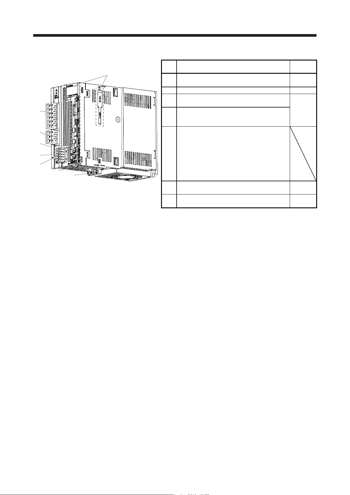
(b) MR-J4-350B(-RJ)
The broken line area is the same as
MR-J4-200B(-RJ) or less.
(1)
(3)
(2)
Side
(4)
(5)
(7)
(6)
No. Name/Application
Detailed
explanation
(1)
Main circuit power connector (CNP1)
Connect the input power supply.
Section 3.1
Section 3.3
(2) Rating plate Section 1.6
(3)
Servo motor power connector (CNP3)
Connect the servo motor.
Section 3.1
Section 3.3
(4)
Control circuit power connector (CNP2)
Connect the control circuit power supply and
regenerative option.
(5)
Charge lamp
When the main circuit is charged, this will light.
While this lamp is lit, do not reconnect the cables.
The lamp may light up when only the control circuit
is powered on. Before wiring or inspection, turn off
the main circuit power and the control circuit power,
and wait for 15 minutes or more until the charge
lamp turns off. Then, check the voltage between P+
and N- using the tester, etc.
(6)
Protective earth (PE) terminal Section 3.1
Section 3.3
(7)
Battery holder
Install the battery for absolute position data backup.
Section
12.2