sh030106u.pdf - 第414页
11. OPT I ONS AND PER IPH ERA L EQU IPM ENT 11 - 9 3 Table 11.4 Servo m otor lea kage curr ent examp le ( lgm) Servo mot or power [kW] Leakage current [mA] 0.05 to 1 0.1 1.2 to 2 0 .2 3 to 3 .5 0 .3 4.2 to 5 0 .5 6 to 7 …
11. OPTIONS AND PERIPHERAL EQUIPMENT
11 - 92
11.15 Earth-leakage current breaker
(1) Selection method
High-frequency chopper currents controlled by pulse width modulation flow in the AC servo circuits.
Leakage currents containing harmonic contents are larger than those of the motor which is run with a
commercial power supply.
Select an earth-leakage current breaker according to the following formula, and ground the servo
amplifier, servo motor, etc. securely.
To minimize leakage currents, make the input and output wires as short as possible, and keep a
distance of 30 cm or longer between the wires and ground.
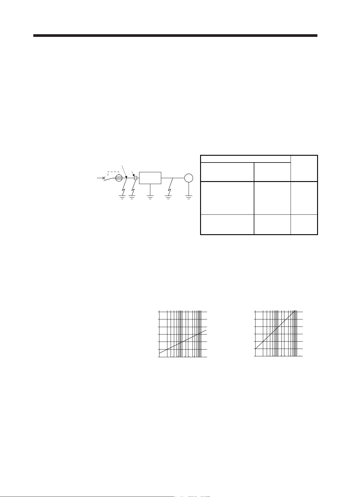
Rated sensitivity current ≥ 10 • {Ig1 + Ign + Iga + K • (Ig2 + Igm)} [mA] ···································· (11.1)
Ign
Noise filter
Wire
Ig1 Iga Ig2 Igm
M
Servo
amplifier
NV
Wire
Earth-leakage current breaker
K
Type
Mitsubishi
Electric
products
Models provided with
harmonic and surge
reduction techniques
NV-SP
NV-SW
NV-CP
NV-CW
NV-HW
1
General models
BV-C1
NFB
NV-L
3
Ig1: Leakage current on the electric channel from the earth-leakage current breaker to the input
terminals of the servo amplifier (Found from Fig. 11.15.)
Ig2: Leakage current on the electric channel from the output terminals of the servo amplifier to the servo
motor (Found from Fig. 11.15.)
Ign: Leakage current when a filter is connected to the input side (4.4 mA per one FR-BIF(-H))
Iga: Leakage current of the servo amplifier (Found from table 11.5.)
Igm: Leakage current of the servo motor (Found from table 11.4.)
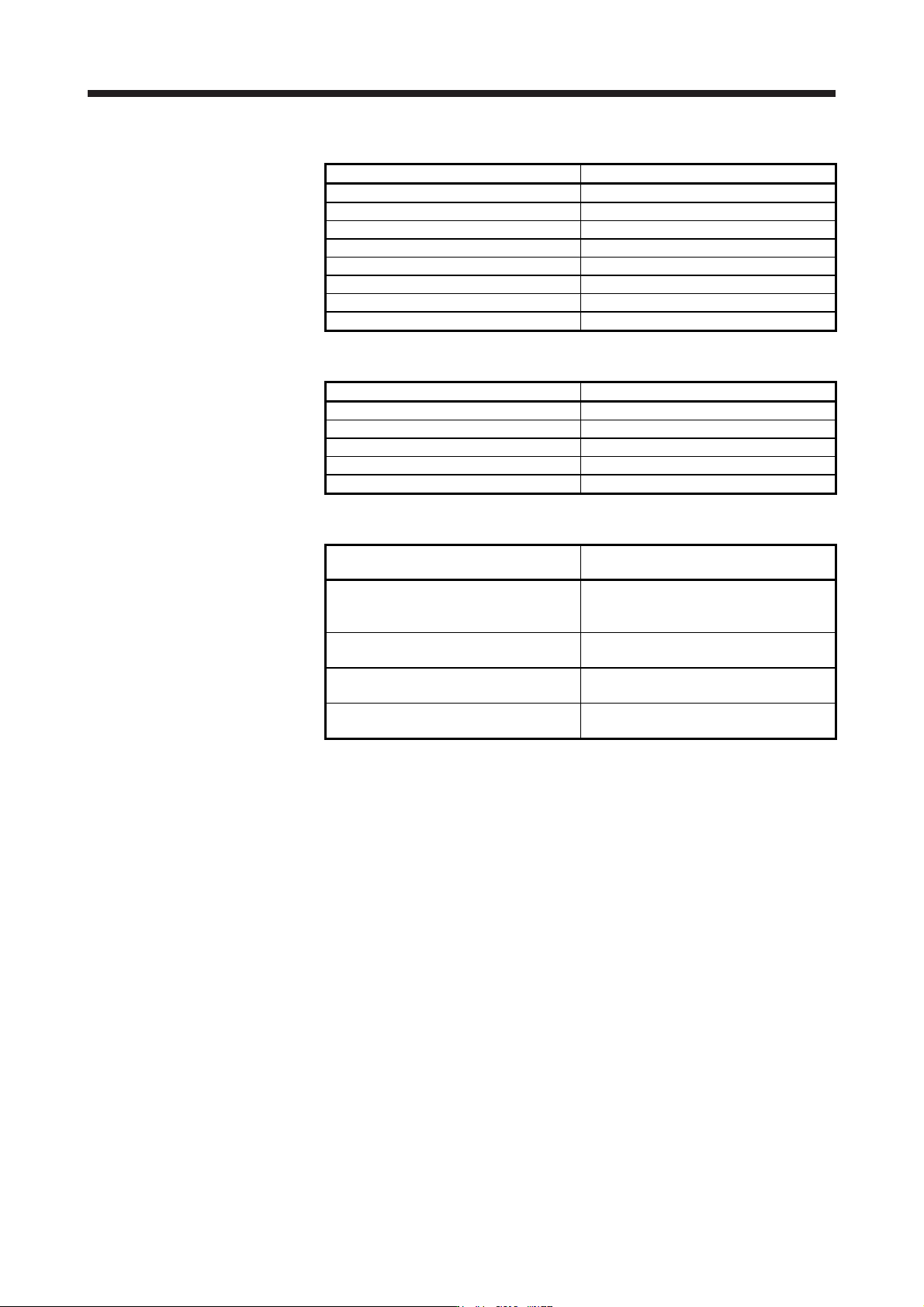
Leakage current [mA]
Cable size [mm ]
2
120
100
80
60
40
20
0
2 5.5 14
3.5 8
38100
22
30
60150
80
120
100
80
60
40
20
0
2
3.5
5.5
8
14
22
38
80
150
30
60
100
Leakage current [mA]
Cable size [mm ]
2
200 V class/100 V class (Note) 400 V class
Note. "I
g
1" of 100 V class servo amplifiers will be 1/2 of 200 V class servo amplifiers.
Fig. 11.15 Example of leakage current per km (lg1, lg2) for CV cable run in metal conduit
11. OPTIONS AND PERIPHERAL EQUIPMENT
11 - 93
Table
11.4 Servo motor leakage current example (lgm)
Servo motor power [kW] Leakage current [mA]
0.05 to 1 0.1
1.2 to 2 0.2
3 to 3.5 0.3
4.2 to 5 0.5
6 to 7 0.7
8 to 11 1.0
12 to 15 1.3
20 to 25 2.3
Table
11.5 Servo amplifier leakage current example (Iga)
Servo amplifier capacity [kW] Leakage current [mA]
0.1 to 0.6 0.1
0.75 to 3.5 0.15
5/7 2
11/15 5.5
22 7
Table
11.6 Earth-leakage current breaker selection example
Servo amplifier
Rated sensitivity current of earth-leakage
current breaker [mA]
MR-J4-10B(-RJ) to MR-J4-350B(-RJ)
MR-J4-60B4(-RJ) to MR-J4-350B4(-RJ)
MR-J4-10B1(-RJ) to MR-J4-40B1(-RJ)
15
MR-J4-500B(-RJ)
MR-J4-500B4(-RJ)
30
MR-J4-700B(-RJ)
MR-J4-700B4(-RJ)
50
MR-J4-11KB(-RJ) to MR-J4-22KB(-RJ)
MR-J4-11KB4(-RJ) to MR-J4-22KB4(-RJ)
100
11. OPTIONS AND PERIPHERAL EQUIPMENT
11 - 94
(2)
Selection example
Indicated below is an example of selecting an earth-leakage current breaker under the following
conditions.
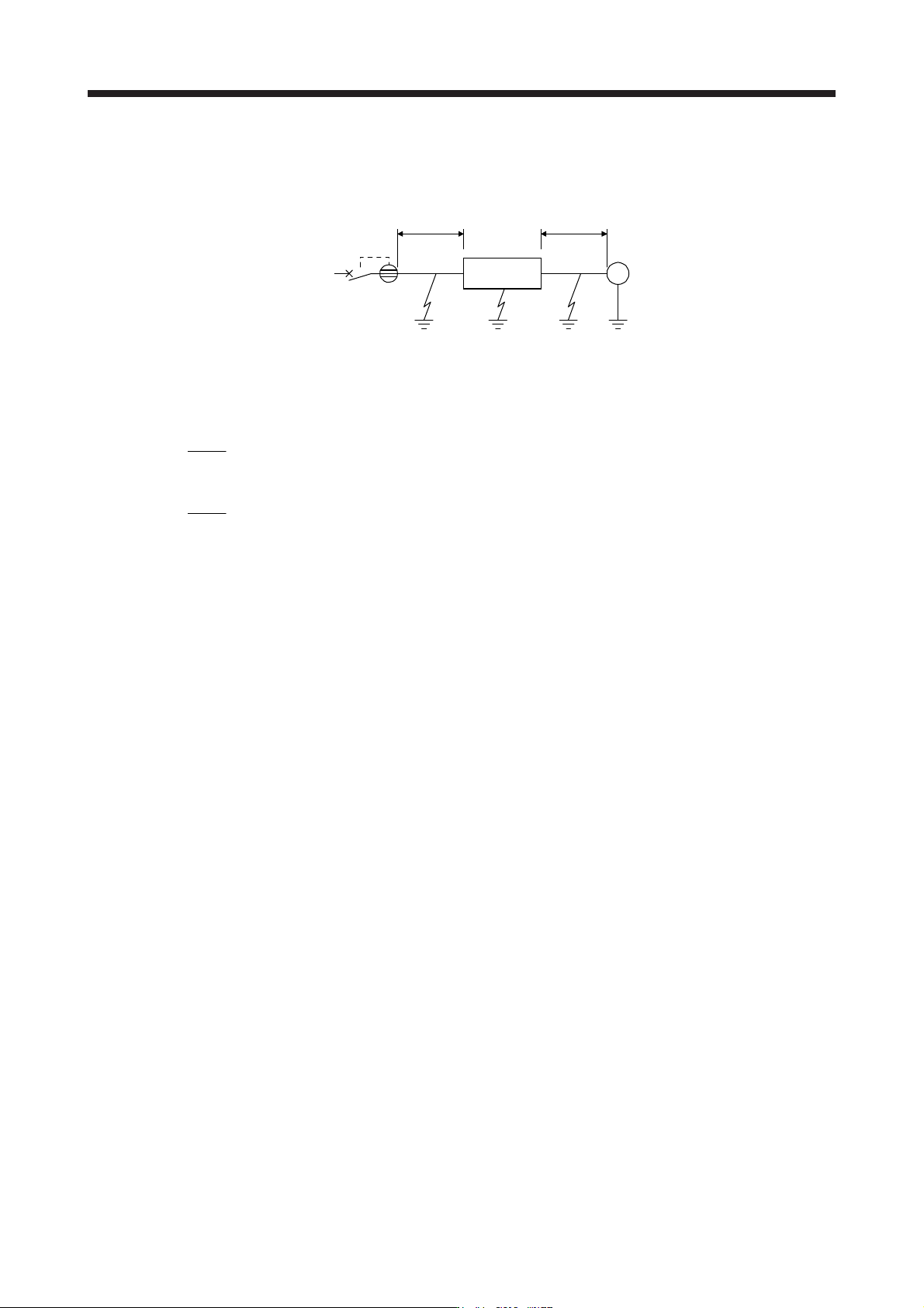
Servo motor
HG-KR43
2 mm
2
× 5 m2 mm
2
× 5 m
M
NV
Ig1 Iga Ig2 Igm
Servo amplifier
MR-J4-40B
Use an ear
th-leakage current breaker designed for suppressing harmonics/surges.
Find the terms of equation (11.1) from the diagram.
Ig1 = 20 •
5
1000
= 0.1 [mA]
Ig2 = 20 •
5
1000
= 0.1 [mA]
Ign = 0 (not used)
Iga = 0.1 [mA]
Igm = 0.1 [mA]
Insert these values in equation (11.1).
Ig ≥ 10 • {0.1 + 0 + 0.1 + 1 • (0.1 + 0.1)}
≥ 4 [mA]
According to the result of calculation, use an earth-leakage current breaker having the rated sensitivity
current (Ig) of 4.0 mA or more.
An earth-leakage current breaker having Ig of 15 mA is used with the NV-SP/SW/CP/CW/HW series.