sh030106u.pdf - 第423页
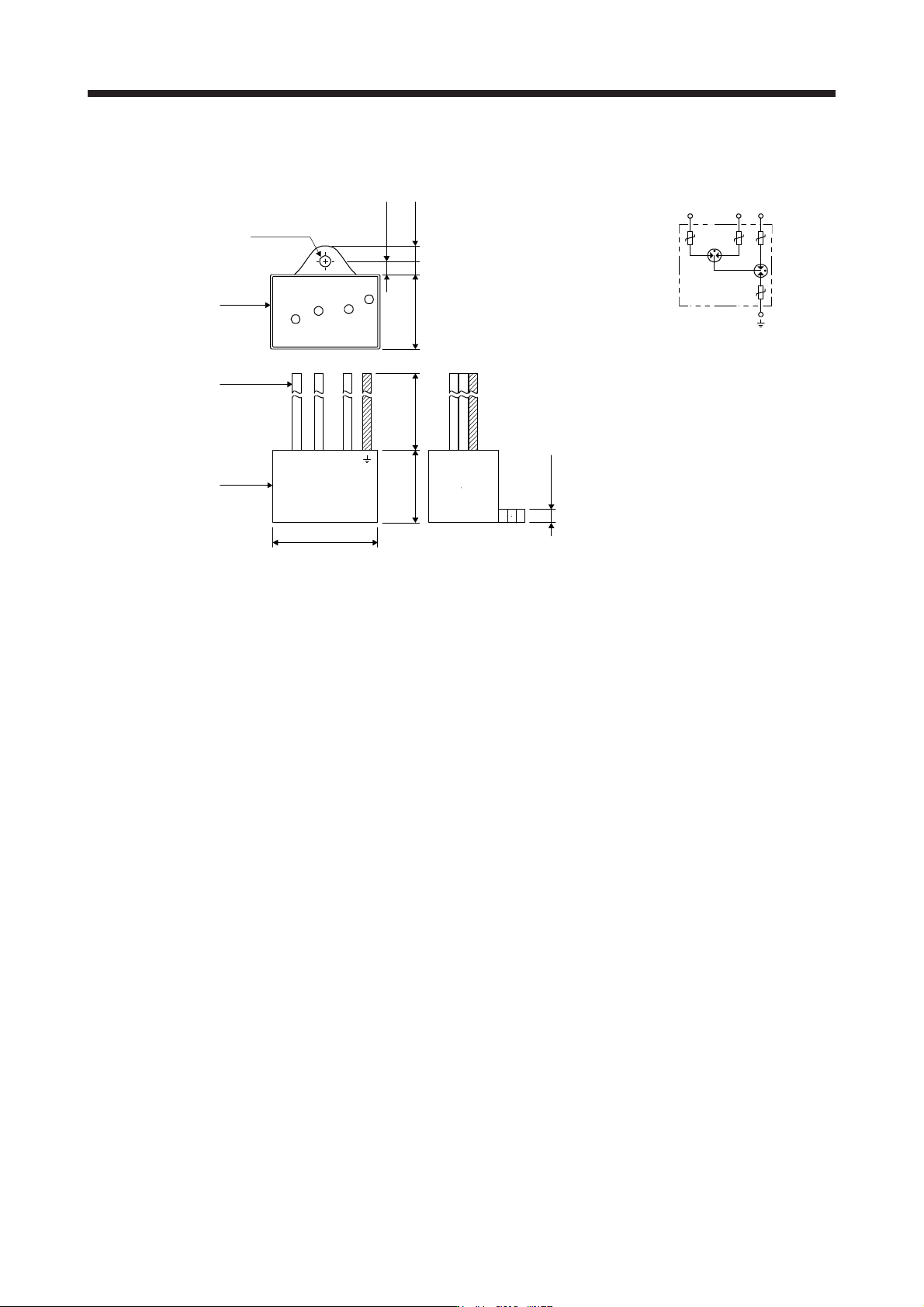
11. OPT I ONS AND PER IPH ERA L EQU IPM ENT 11 - 10 2 (b) Su rge prote ctor RSPD-250-U 4/RSPD-5 00-U4 41 ± 1 28.5 ± 1 28 ± 1 φ 4.2 ± 0.5 5.5 ± 1 11 ± 1 +30 0 200 4.5 ± 0.5 13 2 Lead Case Resin [Unit: mm] 12 3
11. OPTIONS AND PERIPHERAL EQUIPMENT
11 - 101
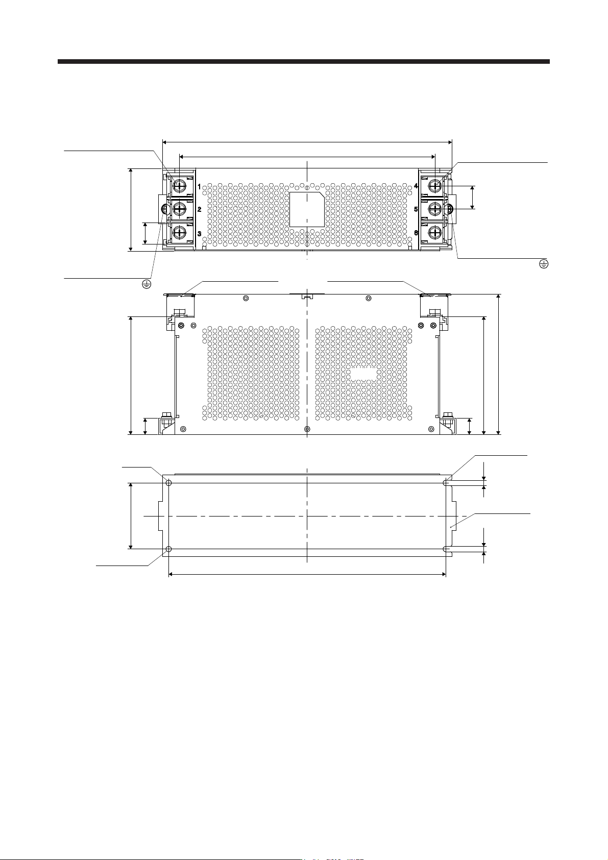
FTB
-100-355-L/FTB-80-355-L
[Unit: mm]
309
350
335 ± 0.5
2-φ6.5
80 ± 0.5
20
143 100
26
6.56.5
20
28
143
170
3-M8 (option-S: hexagon
socket head cap screw)
Output
Protective earth (PE)
M6 (option-S: hexagon
socket head cap screw)
Input
Protective earth (PE)
3-M8 (option-S: hexagon
socket head cap screw)
M6 (option-S: hexagon
socket head cap screw)
Terminal block coverTerminal block cover
Mounting hole
Mounting hole
Mounting plate
(Note)
Model
plate
Note. No heat radiation holes on the opposite face.
11. OPTIONS AND PERIPHERAL EQUIPMENT
11 - 102
(b) Su
rge protector
RSPD-250-U4/RSPD-500-U4
41 ± 1
28.5 ± 1 28 ± 1
φ4.2 ± 0.5
5.5 ± 1
11 ± 1
+30
0
200
4.5 ± 0.5
132
Lead
Case
Resin
[Unit: mm]
123
11. OPTIONS AND PERIPHERAL EQUIPMENT
11 - 103
11.17 Ext
ernal dynamic brake
CAUTION
Use an external dynamic brake for a servo amplifier of MR-J4-11KB(-RJ) to MR-
J4-22KB(-RJ) and MR-J4-11KB4(-RJ) to MR-J4-22KB4(-RJ). Failure to do so will
cause an accident because the servo motor does not stop immediately but coasts
at an alarm occurrence for which the servo motor does not decelerate to stop.
Ensure the safety in the entire equipment. For alarms for which the servo motor
does not decelerate to stop, refer to chapter 8.
The external dynamic brake cannot be used for compliance with SEMI-F47
standard. Do not assign DB (Dynamic brake interlock) in [Pr. PD07] to [Pr. PD09].
Failure to do so will cause the servo amplifier to become servo-off when an
instantaneous power failure occurs.
POINT
EM2 has the same function as EM1 in the torque control mode.
Configure up a sequence which switches off the magnetic contactor of the
external dynamic brake after (or as soon as) the servo-on command has been
turned off at a power failure or a malfunction.
For the braking time taken when the external dynamic brake is operated, refer to
section 10.3.
The external dynamic brake is rated for a short duration. Do not use it very
frequently.
When using the 400 V class external dynamic brake, the power supply voltage is
restricted to 1-phase 380 V AC to 463 V AC (50 Hz/60 Hz).
The external dynamic brake is activated in the following situations: When an
alarm, [AL. E6 Servo forced stop warning], or [AL. E7 Controller forced stop
warning] occurs; or when STO (STO1, STO2), ready-on command, or power is
turned off. Do not use external dynamic brake to stop in a normal operation as it
is the function to stop in emergency.
For a machine operating at the recommended load to motor inertia ratio or less,
the estimated number of usage times of the external dynamic brake is 1000
times while the machine decelerates from the rated speed to a stop once in 10
minutes.
Be sure to enable EM1 (Forced stop 1) after servo motor stops when using EM1
(Forced stop 1) frequently in other than emergency.
(1)
Selection of external dynamic brake
The dynamic brake is designed to bring the servo motor to a sudden stop when a power failure occurs or
the protective circuit is activated, and is built in the 7 kW or less servo amplifier. Since it is not built in t
he
11 kW or more servo amplifier, purchase it separately. Assign DB (Dynamic brake interlock) to any of
CN3-9, CN3-13, and CN3-15 pins in [Pr. PD07] to [Pr. PD09].
Servo amplifier External dynamic brake
Molded-case circuit breaker Fuse (Class T) Fuse (Class K5)
Frame, rated current
Voltage
AC [V]
Current [A]
Voltage
AC [V]
Current [A]
Voltage
AC [V]
MR-J4-11KB(-RJ) DBU-11K
30 A frame 5 A 240 1 300 1 250
MR-J4-15KB(-RJ) DBU-15K
MR-J4-22KB(-RJ) DBU-22K-R1
MR-J4-11KB4(-RJ) DBU-11K-4
30 A frame 5 A 480 1 600 1 600
MR-J4-15KB4(-RJ)
DBU-22K-4
MR-J4-22KB4(-RJ)