sh030106u.pdf - 第425页
11. OPT I ONS AND PER IPH ERA L EQU IPM ENT 11 - 10 4 (2) Conn ection ex ample (a) 200 V class Emer gency stop switch L11 L21 U V W U V W E M Servo amplifier Servo motor L3 L2 L1 (Note 3 ) Powe r supply 13 U 14 V W Exter…
11. OPTIONS AND PERIPHERAL EQUIPMENT
11 - 103
11.17 Ext
ernal dynamic brake
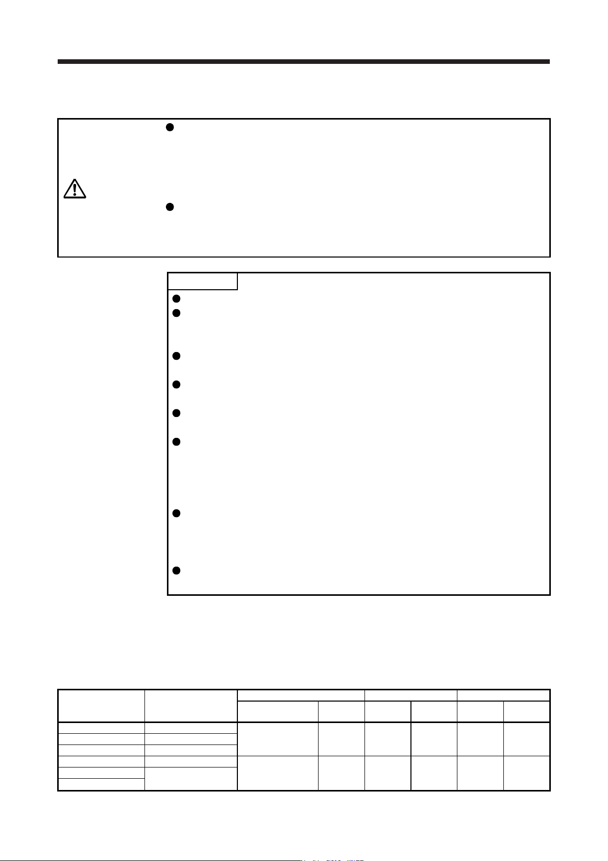
CAUTION
Use an external dynamic brake for a servo amplifier of MR-J4-11KB(-RJ) to MR-
J4-22KB(-RJ) and MR-J4-11KB4(-RJ) to MR-J4-22KB4(-RJ). Failure to do so will
cause an accident because the servo motor does not stop immediately but coasts
at an alarm occurrence for which the servo motor does not decelerate to stop.
Ensure the safety in the entire equipment. For alarms for which the servo motor
does not decelerate to stop, refer to chapter 8.
The external dynamic brake cannot be used for compliance with SEMI-F47
standard. Do not assign DB (Dynamic brake interlock) in [Pr. PD07] to [Pr. PD09].
Failure to do so will cause the servo amplifier to become servo-off when an
instantaneous power failure occurs.
POINT
EM2 has the same function as EM1 in the torque control mode.
Configure up a sequence which switches off the magnetic contactor of the
external dynamic brake after (or as soon as) the servo-on command has been
turned off at a power failure or a malfunction.
For the braking time taken when the external dynamic brake is operated, refer to
section 10.3.
The external dynamic brake is rated for a short duration. Do not use it very
frequently.
When using the 400 V class external dynamic brake, the power supply voltage is
restricted to 1-phase 380 V AC to 463 V AC (50 Hz/60 Hz).
The external dynamic brake is activated in the following situations: When an
alarm, [AL. E6 Servo forced stop warning], or [AL. E7 Controller forced stop
warning] occurs; or when STO (STO1, STO2), ready-on command, or power is
turned off. Do not use external dynamic brake to stop in a normal operation as it
is the function to stop in emergency.
For a machine operating at the recommended load to motor inertia ratio or less,
the estimated number of usage times of the external dynamic brake is 1000
times while the machine decelerates from the rated speed to a stop once in 10
minutes.
Be sure to enable EM1 (Forced stop 1) after servo motor stops when using EM1
(Forced stop 1) frequently in other than emergency.
(1)
Selection of external dynamic brake
The dynamic brake is designed to bring the servo motor to a sudden stop when a power failure occurs or
the protective circuit is activated, and is built in the 7 kW or less servo amplifier. Since it is not built in t
he
11 kW or more servo amplifier, purchase it separately. Assign DB (Dynamic brake interlock) to any of
CN3-9, CN3-13, and CN3-15 pins in [Pr. PD07] to [Pr. PD09].
Servo amplifier External dynamic brake
Molded-case circuit breaker Fuse (Class T) Fuse (Class K5)
Frame, rated current
Voltage
AC [V]
Current [A]
Voltage
AC [V]
Current [A]
Voltage
AC [V]
MR-J4-11KB(-RJ) DBU-11K
30 A frame 5 A 240 1 300 1 250
MR-J4-15KB(-RJ) DBU-15K
MR-J4-22KB(-RJ) DBU-22K-R1
MR-J4-11KB4(-RJ) DBU-11K-4
30 A frame 5 A 480 1 600 1 600
MR-J4-15KB4(-RJ)
DBU-22K-4
MR-J4-22KB4(-RJ)
11. OPTIONS AND PERIPHERAL EQUIPMENT
11 - 104
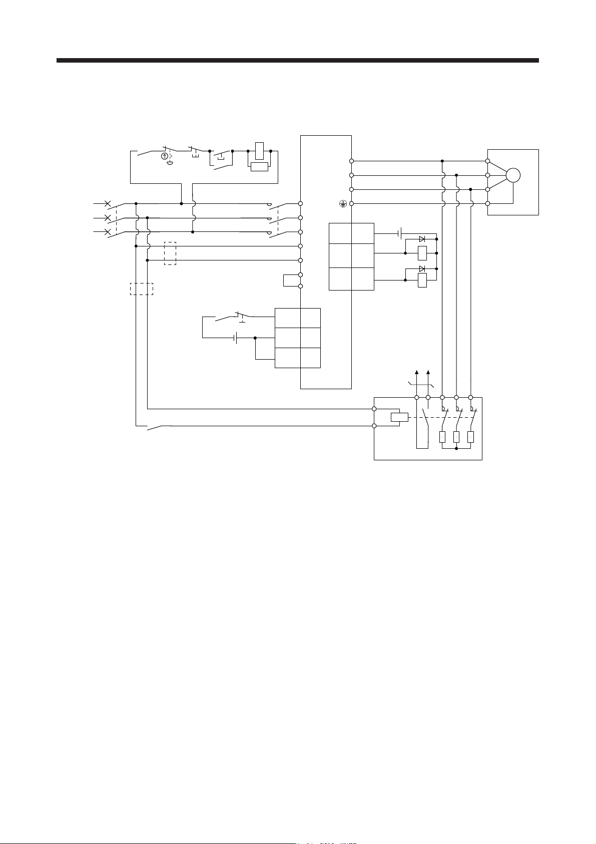
(2) Conn
ection example
(a) 200 V class
Emergency
stop switch
L11
L21
U
V
W
U
V
W
E
M
Servo amplifier
Servo motor
L3
L2
L1
(Note 3)
Powe
r
supply
13 U14 V W
External dynamic brake
a
b
(Note 1)
ALM15
DB
(Note 2,
8)
DOCOM
3
CN3
RA2
MCCB
Operation ready
MC
ALM
RA1
OFF ON
MC
SK
RA1
RA2
MC
Dynamic brake
interlock
(Note 4)
(Note 5)
Main circuit
power supply
24 V DC (Note 6)
5
DICOM
10
EM2 20
DICOM
CN3
24 V DC (Note 6)
P3
P4
(Note 7)
(Note 9)
(Note 9)
Note 1. Terminals 13 and 14 are normally open contact outputs. If the external dynamic brake is seized, terminals 13 and 14 will open.
Therefore, confi
g
ure up an external sequence to prevent servo-on.
2.
A
ssi
g
n DB
(
D
y
namic brake interlock
)
in [Pr. PD07] to [Pr. PD09].
3. For the power suppl
y
specifications, refer to section 1.3.
4. Depending on the main circuit voltage and operation pattern, bus voltage decreases, and that may cause the forced st
op
deceleration to shift to the dynamic brake deceleration. When dynamic brake deceleration is not required, slow the time to turn
o
ff the ma
g
netic contactor.
5. Turn off EM2 when the main power circuit power suppl
y
is off.
6. The illustration of the 24 V DC power supply is divided between input signal and output signal for convenience. However, they
can be confi
g
ured b
y
one.
7. Between P3 and P4 is connected by default. When using the power factor improving DC reactor, remove the short
bar
between P3 and P4. Refer to section 11.11 for details. Additionally, a power factor improving DC reactor and power factor
i
mprovin
g
AC reactor cannot be used simultaneousl
y
.
8. The external dynamic brake cannot be used for compliance with SEMI-F47 standard. Do not assign DB (Dynamic brake
interlock) in [Pr. PD07] to [Pr. PD09]. Failure to do so will cause the servo amplifier to become servo-off when
an
i
nstantaneous power failure occurs.
9. Install an overcurrent protection device (molded-case circuit breaker, fuse, or others) to protect the branch circuit. (Refer t
o
s
ection 11.10 and
(
1
)
in this section.
)
11. OPTIONS AND PERIPHERAL EQUIPMENT
11 - 105
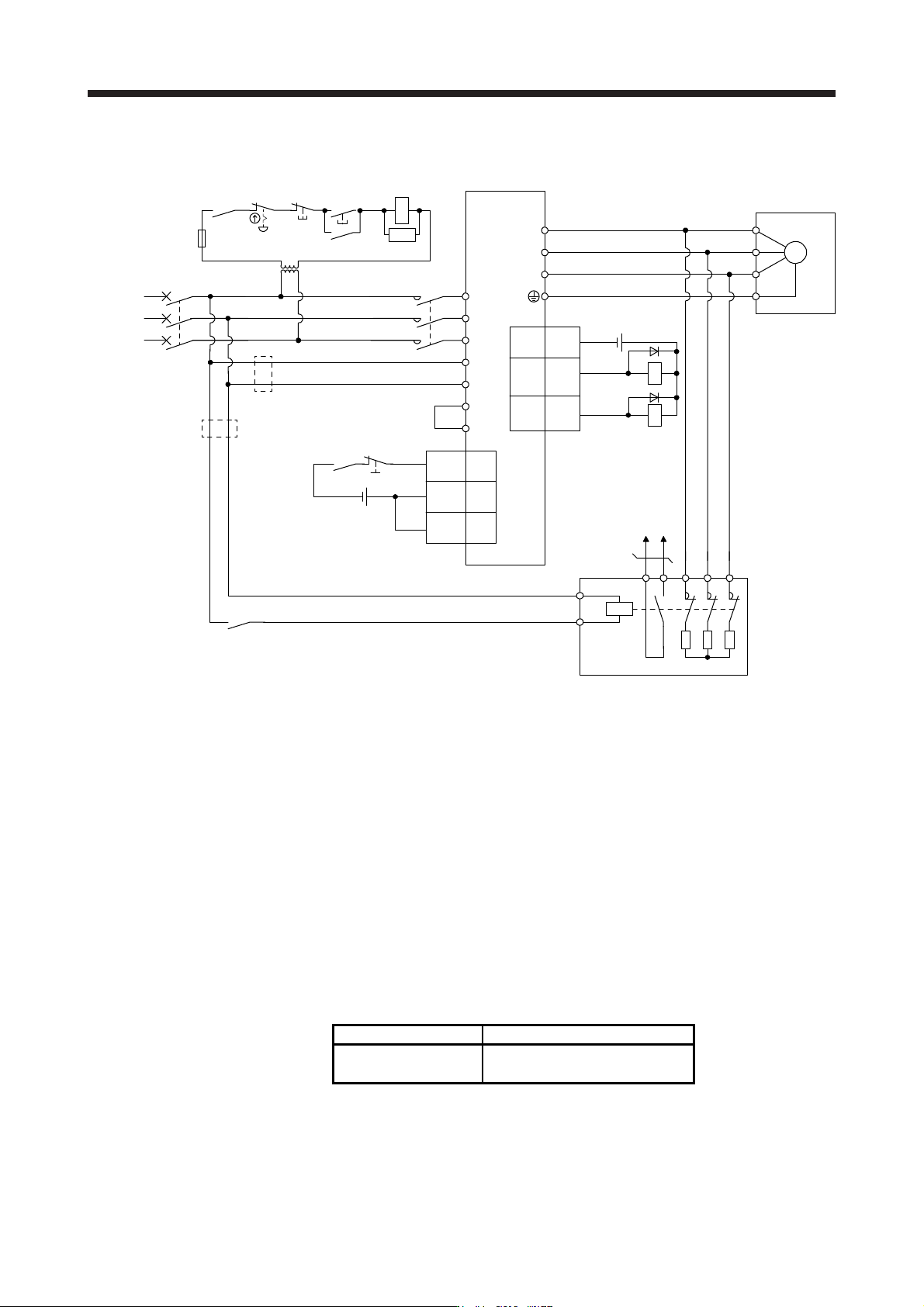
(b) 400
V class
Emergency
stop switch
L11
L21
U
V
W
U
V
W
E
M
Servo amplifier
Servo motor
L3
L2
L1
(Note 3)
Power
supply
13 U14 V W
External dynamic brake
a
b
(Note 1)
ALM15
DB
(Note 2,
10)
DOCOM
3
CN3
RA2
MCCB
Operation ready
MC
ALM
RA1
OFF ON
MC
SK
RA1
RA2
MC
Dynamic brake
interlock
(Note 4)
(Note 5)
Main circuit
power supply
24 V DC (Note 6)
5
DICOM 10
EM2 20
DICOM
CN3
24 V DC (Note 6)
P3
P4
(Note 7)
(Note 8) Step-down
transformer
(Note 9)
(Note 11)
(Note 11)
Note 1. Terminals 13 and 14 are normally open contact outputs. If the external dynamic brake is seized, terminals 13 and 14 will open.
Therefore, confi
g
ure an external sequence to prevent servo-on.
2.
A
ssi
g
n DB
(
D
y
namic brake interlock
)
in [Pr. PD07] to [Pr. PD09].
3. For power suppl
y
specifications, refer to section 1.3.
4. Depending on the main circuit voltage and operation pattern, bus voltage decreases, and that may cause the forced st
op
deceleration to shift to the dynamic brake deceleration. When dynamic brake deceleration is not required, slow the time to turn
o
ff the ma
g
netic contactor.
5. Turn off EM2 when the main power circuit power suppl
y
is off.
6. The illustration of the 24 V DC power supply is divided between input signal and output signal for convenience. However, they
can be confi
g
ured b
y
one.
7. Between P3 and P4 is connected by default. When using the power factor improving DC reactor, remove the short
bar
between P3 and P4. Refer to section 11.11 for details. Additionally, a power factor improving DC reactor and power factor
i
mprovin
g
AC reactor cannot be used simultaneousl
y
.
8. Stepdown transformer is required when the coil volta
g
e of the ma
g
netic contactor is 200 V class.
9. The power supply voltage of the inside magnet contactor for 400 V class external dynamic brake DBU-11K-4 and DBU-22K
-4
is restricted as follows. When usin
g
these external d
y
namic brakes, use them within the ran
g
e of the power suppl
y
.
External dynamic brake Power supply voltage
DBU-11K-4
DBU-22K-4
1-phase 380 V AC to 463 V AC, 50
Hz
/60 Hz
10. The external dynamic brake cannot be used for compliance with SEMI-F47 standard. Do not assign DB (Dynamic brake
interlock) in [Pr. PD07] to [Pr. PD09]. Failure to do so will cause the servo amplifier to become servo-off when
an
instantaneous power failure occurs.
11. Install an overcurrent protection device (molded-case circuit breaker, fuse, or others) to protect the branch circuit. (Refer t
o
section 11.10 and
(
1
)
in this section.
)