sh030106u.pdf - 第438页
11. OPT I ONS AND PER IPH ERA L EQU IPM ENT 11 - 11 7 (d) Mountin g dimens iona l diagr am [Unit: mm] Approx. 58 510 580 12 236 280 Approx. 260 84 194 20 145 Approx. 400 35 3.2 105 155 Approx. 260 Approx. 11.5 Servo ampl…
11. OPTIONS AND PERIPHERAL EQUIPMENT
11 - 116
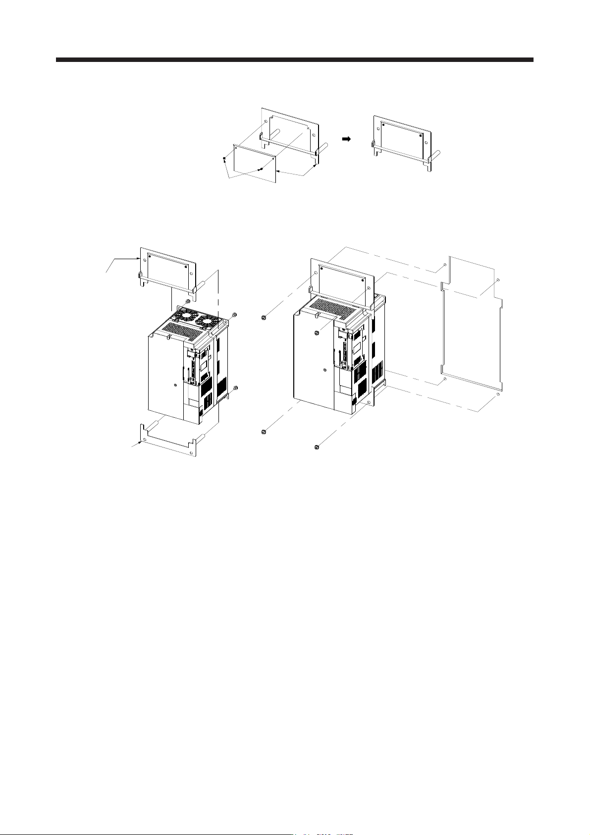
(b) How to as
semble the attachment for panel through attachment
Screw
(2 places)
Attachment
(c)
Mounting method
Fit using the
assembling
screws.
Attachment
Servo
amplifier
Attachment
Servo
amplifier
Punched
hole
Cabine
t
a. Assembling the panel through attachment b. Mounting it to inside cabinet
11. OPTIONS AND PERIPHERAL EQUIPMENT
11 - 117
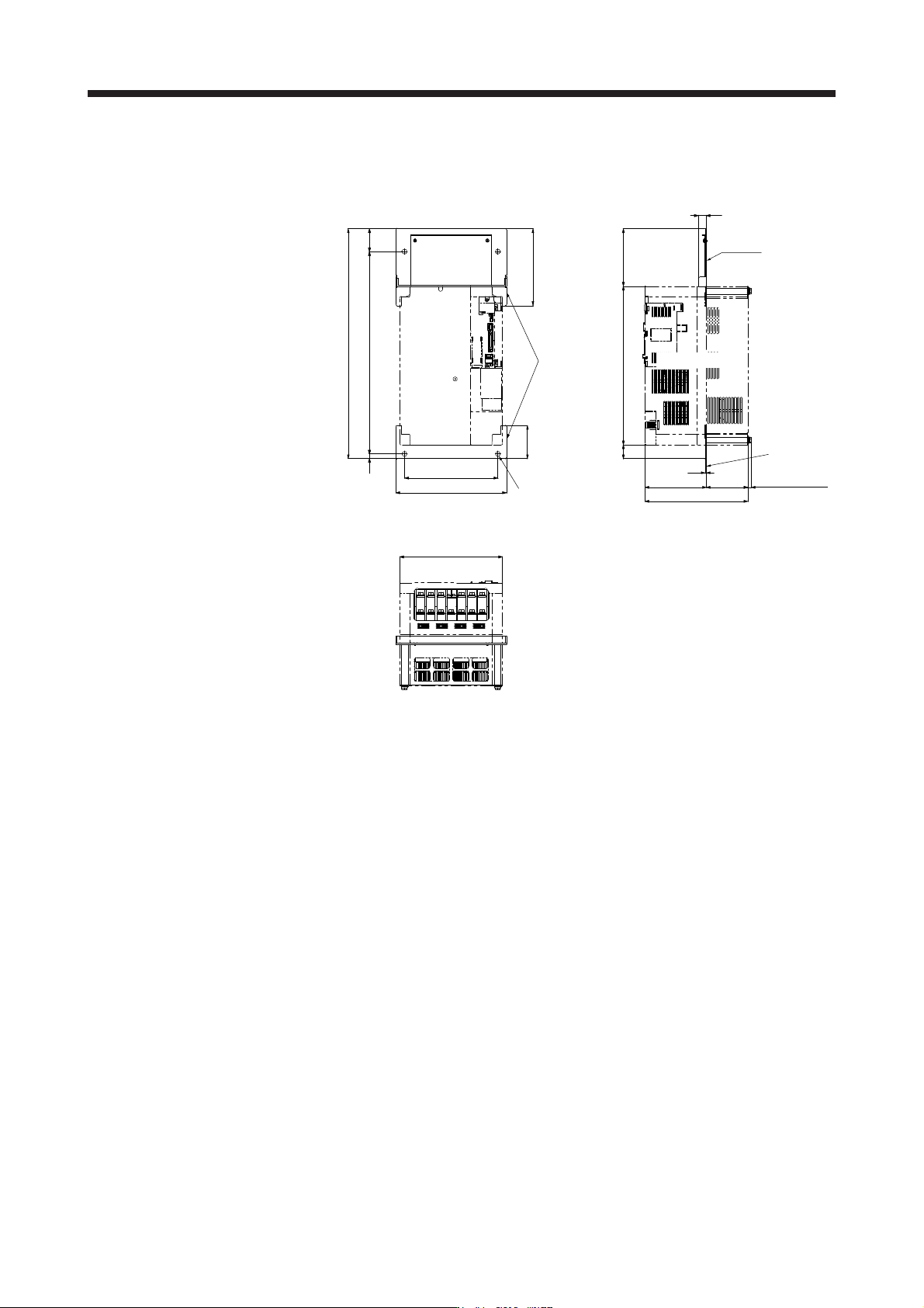
(d)
Mounting dimensional diagram
[Unit: mm]
Approx. 58
510
580
12
236
280
Approx. 260
84
194
20
145
Approx. 400
35
3.2
105155
Approx. 260
Approx. 11.5
Servo
amplifier
Servo amplifier
Mounting
hole
Panel
Panel
Attachment
11. OPTIONS AND PERIPHERAL EQUIPMENT
11 - 118
11.19 Mul
tifunction regeneration converter FR-XC-(H)
POINT
For details on the multifunction regeneration converter (FR-XC-(H)), refer to "FR-
XC INSTRUCTION MANUAL (IB(NA)-0600668ENG)".
11.19.1 Mul
tifunction regeneration converters and dedicated stand-alone reactors
Install a dedicated stand-alone reactor on the multifunction regeneration converter FR-XC-(H) according to
the following table.
Multifunction regeneration
converter
Dedicated stand-alone
reactor
FR-XC-7.5K FR-XCL-7.5K
FR-XC-11K FR-XCL-11K
FR-XC-15K FR-XCL-15K
FR-XC-22K FR-XCL-22K
FR-XC-30K FR-XCL-30K
FR-XC-37K FR-XCL-37K
FR-XC-55K FR-XCL-55K
FR-XC-H7.5K FR-XCL-H7.5K
FR-XC-H11K FR-XCL-H11K
FR-XC-H15K FR-XCL-H15K
FR-XC-H22K FR-XCL-H22K
FR-XC-H30K FR-XCL-H30K
FR-XC-H37K FR-XCL-H37K
FR-XC-H55K FR-XCL-H55K
11.19.2 P
recautions
Set the FR-XC-(H) to the common bus regeneration mode by turning on switch 1 of the function
selecting switch (SW2).
Do not supply power to the main circuit power supply terminals (L1/L2/L3) of the servo amplifier. Doing
so may fail the servo amplifier and the FR-XC-(H).
Connect the polarities of the DC power supply between the FR-XC-(H) and the servo amplifier correctly.
Failing to do so may fail the FR-XC-(H) and the servo amplifier.
For 400 V, use the rated voltage and permissible fluctuation of the input power supply within the
following range.
Rated voltage: 3-phase 380 V to 480 V, 50 Hz/60 Hz
Permissible fluctuation: 3-phase 323 V to 528 V, 50 Hz/60 Hz
11.19.3 Servo amplifier settings
When using the FR-XC-(H), set the parameters as follows.
[Pr. PA02]: "_ _ 0 1"
[Pr. PA04]: "0 0 _ _"
[Pr. PC20]: "_ _ _ 1"