sh030106u.pdf - 第441页
11. OPT I ONS AND PER IPH ERA L EQU IPM ENT 11 - 1 20 (b) Calcu late the tot al output p ower of the serv o motors from t he run ning power and r egenerativ e pow er of each s ervo mot or. -15 kW -15 kW -15 kW 0.1 s 0.1 …

11. OPTIONS AND PERIPHERAL EQUIPMENT
11 - 119
11.19.4 Capac
ity selection
(1) Selection conditions
The multifunction regeneration converter FR-XC-(H) can be used with 200 V class servo amplifiers with
capacities of 100 W to 22 kW and 400 V class servo amplifiers with capacities of 600 W to 22 kW. Select
a multifunction regeneration converter based on the following selection conditions.
Number of servo amplifiers to be connected to one FR-XC-(H) is 10 or less
Total capacity of servo amplifiers [kW] ≤ Total capacity of servo amplifiers that can be connected to the
FR-XC-(H) [kW]
Effective value of the total servo motor output power [kW] ≤ Continuous output of the FR-XC-(H) [kW]
Maximum value of the total servo motor output power [kW] ≤ Instantaneous maximum output of the
FR-XC-(H) [kW]
Item
FR-XC-(H)_
7.5K 11K 15K 22K 30K 37K 55K
Rated capacity [kW] 7.5 11 15 22 30 37 55
Maximum number of connectable servo amplifiers 10
Total capacity of connectable servo amplifiers
[kW] (Note)
3.5 (5.5) 5.5 (7.5) 7.5 (11) 22 30 37 55
Continuous output [kW] (Note) 3.5 (5.5) 5.5 (7.5) 7.5 (11) 18.5 22 30 45
Instantaneous maximum output [kW] 11.25 16.5 22.5 33 45 55.5 82.5
Note. Values in parentheses are when six servo amplifiers or less are connected.
(2)
Selection example
The following information explains how to select a multifunction regeneration converter to connect to the
servo amplifiers listed below.
Servo amplifier Servo motor
MR-J4-500B HG-SR502
MR-J4-500B HG-SR502
MR-J4-11KB HG-JR11K1M
MR-J4-22KB HG-JR22K1M
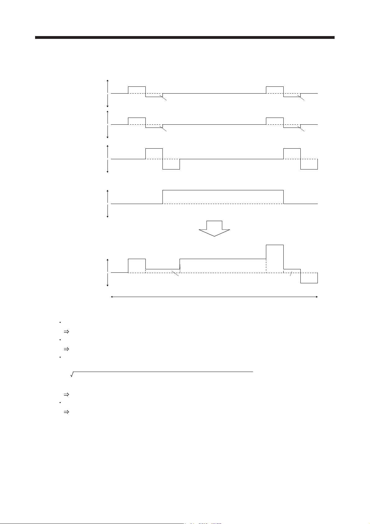
(a) Calc
ulate the running power and regenerative power from the servo motor speed and torque with the
following formulas.
For rotary servo motors
Running power and regenerative power [W] = Servo motor speed [r/min] × Torque [N•m]/9.55
For linear servo motors
Running power and regenerative power [W] = Servo motor speed [m/s] × Thrust [N]
(Running power is indicated by positive values, and regenerative power is indicted by negative
values.)
11. OPTIONS AND PERIPHERAL EQUIPMENT
11 - 120
(b) Calcu
late the total output power of the servo motors from the running power and regenerative power
of each servo motor.
-15 kW
-15 kW-15 kW
0.1 s
0.1 s
5 kW
0.1 s
40 kW
0.5 s
0.7 s
0.6 s
0.2 s0.3 s
0.1 s
0.1 s
0.2 s
0.1 s
0.1 s
0.1 s
0.1 s
0.1 s
0.1 s
5 kW
20 kW
20 kW
15 kW
-5 kW
10 kW
0.1 s
0.1 s
0.1 s
-5 kW
10 kW
15 kW
20 kW
MR-J4-500B/
HG-SR502
MR-J4-11KB/
HG-JR11K1M
MR-J4-22KB/
HG-JR22K1M
0.2 s
0.1 s
0.6 s
0.1 s 0.1 s
0.1 s-5 kW
10 kW
0.1 s 0.1 s
-5 kW
10 kW
MR-J4-500B/
HG-SR502
0.1 s
0.6 s
Power running
energy
Regenerative
power
Power running
energy
Regenerative
power
Power running
energy
Regenerative
power
Power running
energy
Regenerative
power
1.2 s per cycle
Power running
energy
Regenerative
power
Total output power
of servo motors
Total of each servo motor output
(c)
Select a multifunction regeneration converter based on the selection conditions.
Number of servo amplifiers: 4 ≤ 10
Number of servo amplifiers OK.
Total capacity of servo amplifiers [kW] = 5 kW + 5 kW + 11 kW + 22 kW = 43 kW
FR-XC-55K
Effective value of the total servo motor output power [kW]
=
(20
2
× 0.1 + 5
2
× 0.2 + 20
2
× 0.5 + 40
2
× 0.1 + 5
2
× 0.1 + (-15)
2
× 0.1)/1.2 = 18.93 kW
FR-XC-30K or more
Maximum value of the total servo motor output power [kW] = 40 kW
FR-XC-30K or more
Therefore, the multifunction regeneration converter selected should be the "FR-XC-55K".
11. OPTIONS AND PERIPHERAL EQUIPMENT
11 - 121
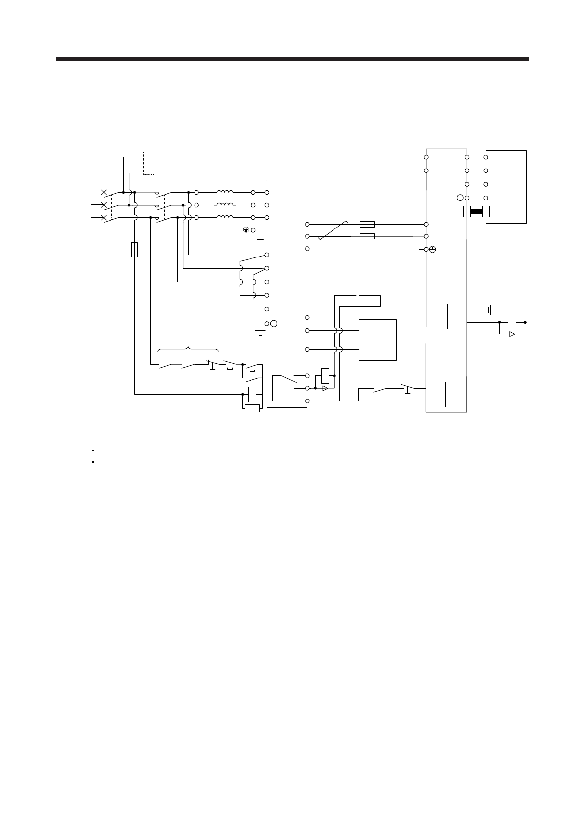
11.19.5 Conn
ection diagrams
(1) 200 V class
T/L3
S/L2
R/L1
T2/L32
MCMCCB
S2/L22
R2/L12
FR-XCL
MC
RA2RA1
EM1
MC
SK
RA1
EM1
R2/L12
S2/L22
N/-
P4
RYB
RYA
SE
P/+
T2/L32
R/L1
S/L2
T/L3
L11
L21
P4
N-
U
V
W
EM1
R1/L11
S1/L21
U
V
W
E
CN2
FR-XC
DICOM
B
C
A
RA1
DOCOM
ALM
RA2
3-phase
200 V AC
to
240 V AC
Off
On
Servo motor
Servo amplifier
Controller
24 V DC
24 V DC
24 V DC
(Note 6)
(Note 11)
(Note 10)
(Note 1)
(Note 8)
(Note 2)
(Note 9)
(Note 7)
(Note 1)
(Note 3)
(Note 7)
(Note 1, 5)
(Note 7)
(Note 4)
Note 1. Configure a sequence that shuts off the main circuit power supply in the following situations:
When an alarm occurs in the FR-XC or servo amplifier
When EM1
(
Forced stop 1
)
is enabled.
2. Confi
g
ure a sequence that shifts the status to servo-on once the F
R
-XC is read
y
.
3. Ensure that the servo motor stops with a forced stop input of the servo amplifier when an alarm occurs in the FR-XC. If the
controller does not have an emer
g
enc
y
stop input, use the forced stop input of the servo amplifier to stop the servo motor.
4. When usin
g
the FR-XC, remove the wire between P3 and P4.
5. To use EM1
(
Forced stop 1
)
, set [Pr. PA04] to "0 0 _ _".
6. If wires used for L11 and L21 are thinner than wires used for L1, L2, and L3, use a molded-case circuit breaker.
7.
A
lthough the diagram shows the input signal and the output signal each using a separate 24 V DC power supply for illustrative
purposes, the s
y
stem can be confi
g
ured to use a sin
g
le 24 V DC power suppl
y
.
8. Remove the R1/L11 and S1/L21
j
umpers when usin
g
a dedicated power suppl
y
for the control circuit.
9. Do not connect an
y
thin
g
to the P4 terminal of the FR-XC.
10. Install a fuse on each wire between the FR-XC and servo amplifier.
11. Make sure to wire the built-in regenerative resistor when using servo amplifiers with a capacity of 7 kW or less. (factory-wi
red)
(
5 kW or less: between P+ and D, 7 kW: between P+ and C
)