sh030106u.pdf - 第460页
13. USIN G STO FUNCTI ON 13 - 7 13.3.2 Ext ernal I/O signa l connec tion ex ample using a n MR-J3-D0 5 safety log ic unit POINT This conn ectio n is f or sourc e i nterface. F or the oth er I/O signa ls, refer to the con…
13. USING STO FUNCTION
13 - 6
13.3 Connection example
POINT
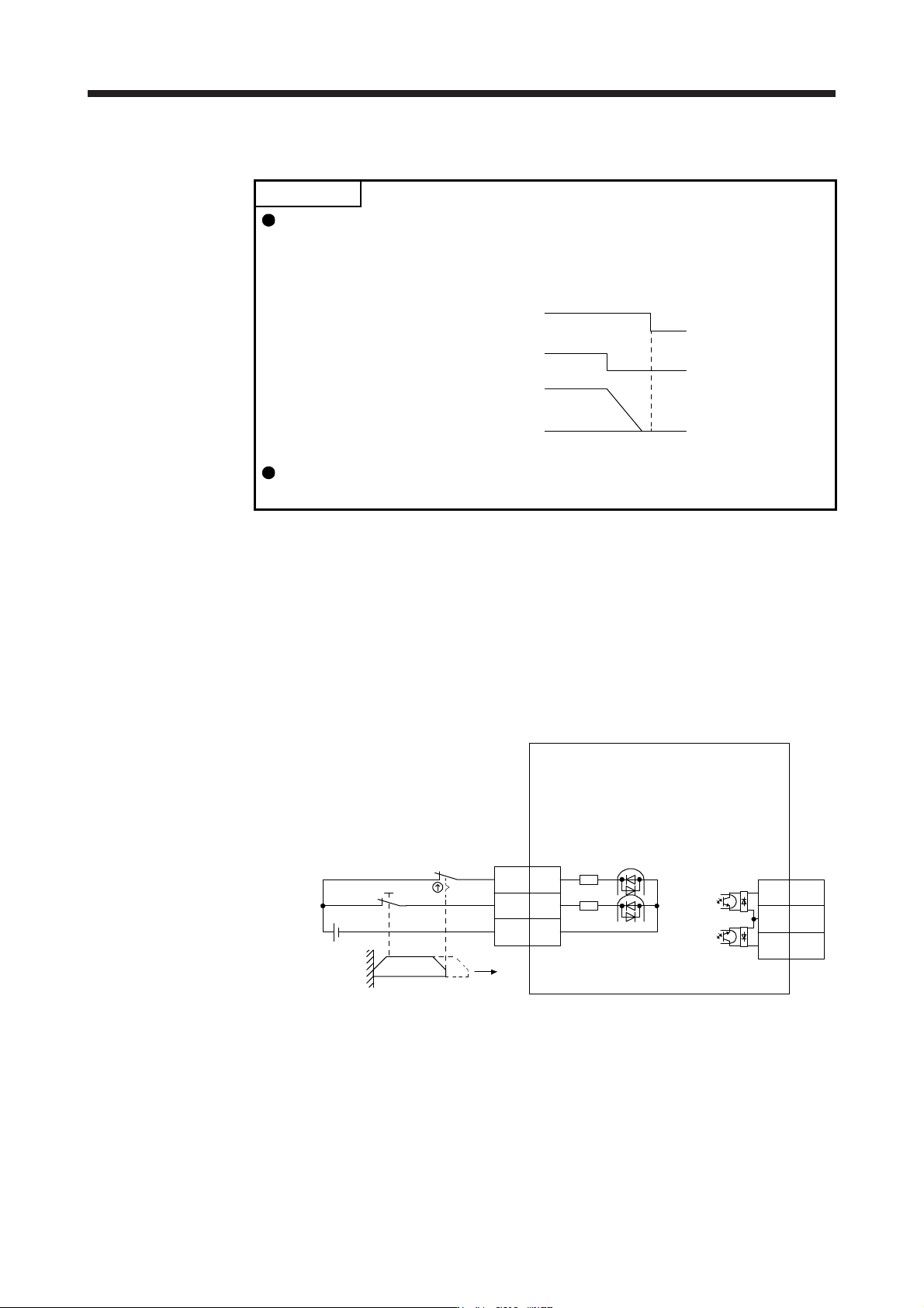
Turn off STO (STO1 and STO2) after the servo motor stops by the servo off
state or with forced stop deceleration by turning off EM2 (Forced stop 2).
Configure an external sequence that has the timings shown as below using an
external device such as the MR-J3-D05 safety logic unit.
STO1/STO2
ON
OFF
ON
OFF
EM2
0 r/min
Servo motor
speed
If STO is turned off during operation, the servo motor is in dynamic brake stop
(stop category 0), and [AL. 63 STO timing error] will occur.
13.3.1 Connection example for CN8 connector
This servo amplifier is equipped with the connector (CN8) in accordance with the STO function. When this
connector is used with a certified external safety relay, power to the motor can be safely removed and
unexpected restart can be prevented. The safety relay used should meet the applicable safety standards and
have forcibly guided or mirror contacts for the purpose of error detection.
In addition, the MR-J3-D05 safety logic unit can be used instead of a safety relay for implementation of
various safety standards. Refer to app. 5 for details.
The following diagram is for source interface. For sink interface, refer to section 13.4.1.
STO1
STO2
CN8
8
6
TOFCOM
7
TOFB2
TOFB1
STO1
CN8
4
STO2
5
STOCOM
3
Approx.
3.0 kΩ
24 V DC
Door
Open
(Note 2)
(Note 2)
(Note 3)
(Note 1)
Approx.
3.0 kΩ
Servo amplifier
Note 1. By using TOFB, whether the servo is in the STO state can be confirmed. For connection
examples, refer to section 13.3.2 to 13.3.4. The safety level depends on the setting value
of [Pr. PF18 STO diagnosis error detection time] and whether STO input diagnosis by
TOFB output is performed or not. For details, refer to the Function column of [Pr. PF18] in
section 5.2.6.
2. When using the STO function, turn off STO1 and STO2 at the same time. Turn off STO1
and STO2 after the servo motor stops by the servo off state or with forced stop
deceleration b
y
turnin
g
off EM2
(
Forced stop 2
)
.
3. Confi
g
ure the interlock circuit so that the door is open after the servo motor is stopped.

13. USING STO FUNCTION
13 - 7
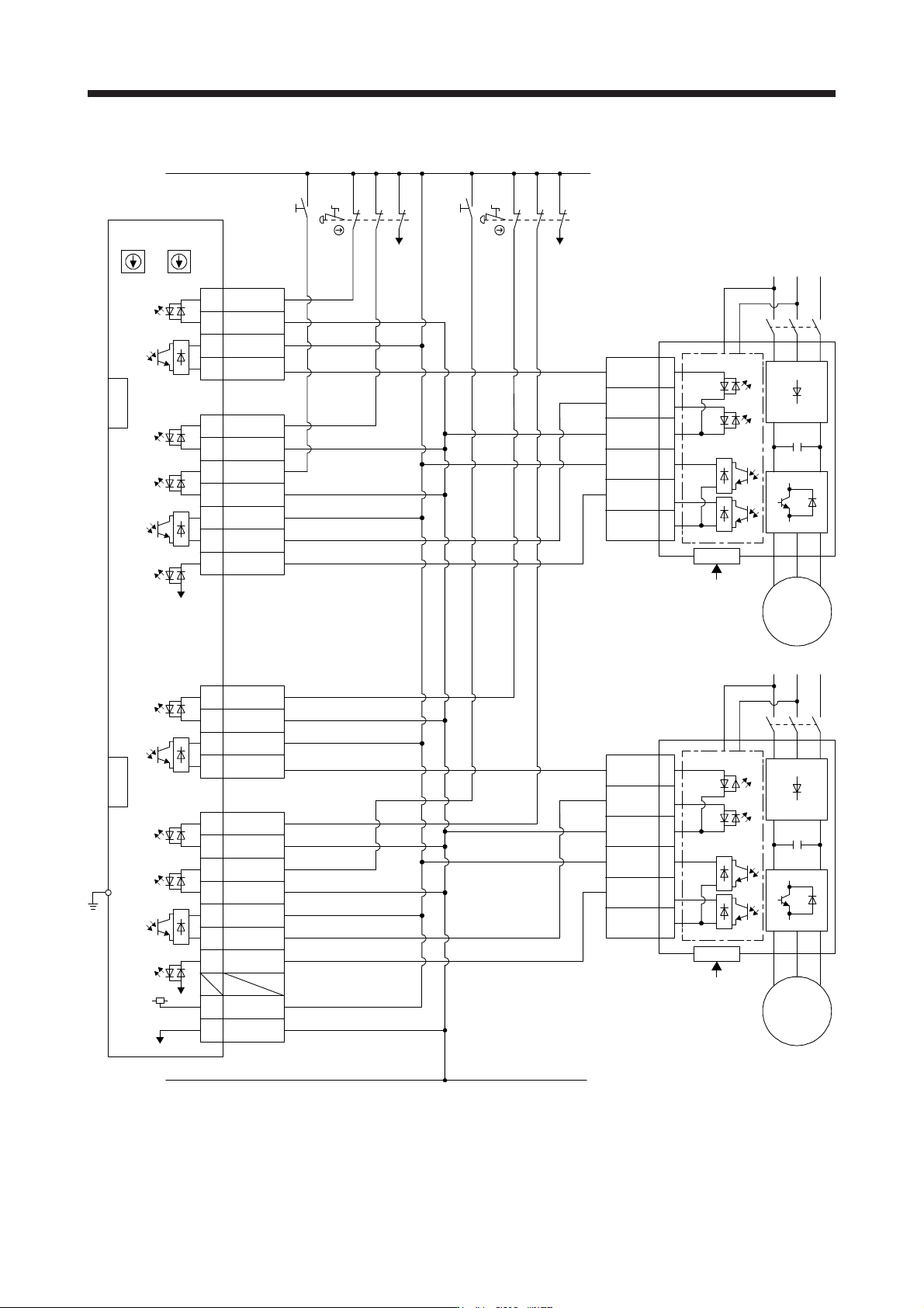
13.3.2 External I/O signal connection example using an MR-J3-D05 safety logic unit
POINT
This connection is for source interface. For the other I/O signals, refer to the
connection examples in section 3.2.2.
13. USING STO FUNCTION
13 - 8
(1) Connection example
STO1
4
5
3
6
7
8
CN3
EM2 (B-axis)
CN8
SDO1A+4A
4B SDO1A-
SDI1A+1A
1B SDI1A-
SDI2A+
SRESA+
SDO2A+
TOFA
3A
3B
1A
1B
6A
6B
8A
SDI2A-
SDO2A-
SRESA-
CN9
CN10
STO1
TOFB2
TOFCOM
STO2
STOCOM
TOFB1
Servo amplifier
SW1
FG
4
5
3
6
7
8
CN3
EM2 (A-axis)
CN8
TOFB2
TOFCOM
STO2
STOCOM
TOFB1
Servo amplifier
SDO1B+3A
3B SDO1B-
SDI1B+2A
2B SDI1B-
SDI2B+
SRESB+
SDO2B+
TOFB
4A
4B
2A
2B
5A
5B
8B
+24V7A
0V7B
SDI2B-
SDO2B-
SRESB-
CN9
CN10
SW2
MR-J3-D05
(Note 1) (Note 1)
(Note 2) (Note 2)
S1
24 V
0 V
RESA
STOA
S3
RESB
STOB
MC
M
Servo motor
MC
M
Servo motor
Control circuit
Control circuit
S4
S2
CN8A
CN8B
EM2
(A-axis)
EM2
(B-axis)
Note 1. Set the delay time of STO output with SW1 and SW2. These switches are located in a recessed area to prevent accidental
settin
g
chan
g
es.
2. To release the STO state
(
base circuit shut-off
)
, turn RESA and RESB on and turn them off.