sh030106u.pdf - 第461页
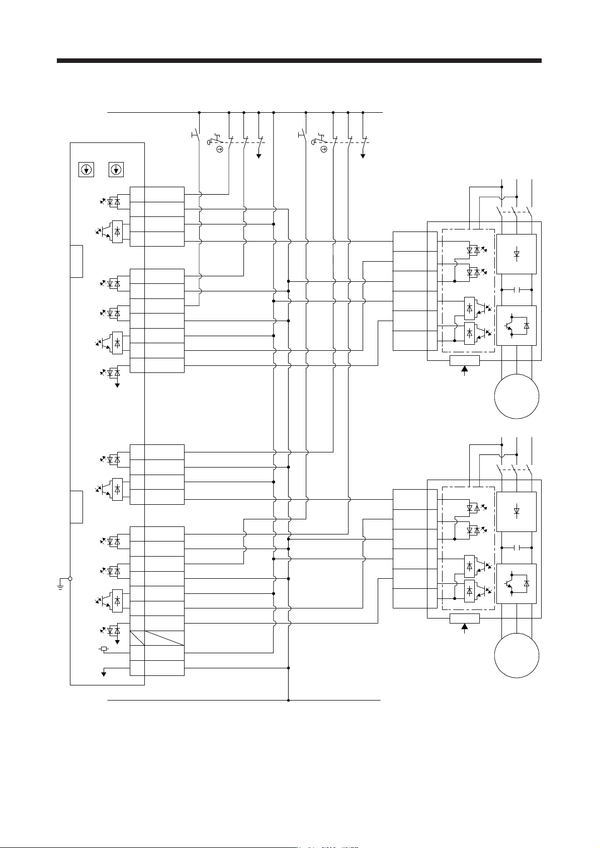
13. USIN G STO FUNCTI ON 13 - 8 (1) Connectio n exampl e STO1 4 5 3 6 7 8 CN3 EM2 (B-axis) CN8 SDO1A+ 4A 4B SDO1A- SDI1A+ 1A 1B SDI1A- SDI2A+ SRESA+ SDO2A+ TOFA 3A 3B 1A 1B 6A 6B 8A SDI2A- SDO2A- SRESA- CN9 CN10 STO1 TOF…

13. USING STO FUNCTION
13 - 7
13.3.2 External I/O signal connection example using an MR-J3-D05 safety logic unit
POINT
This connection is for source interface. For the other I/O signals, refer to the
connection examples in section 3.2.2.
13. USING STO FUNCTION
13 - 8
(1) Connection example
STO1
4
5
3
6
7
8
CN3
EM2 (B-axis)
CN8
SDO1A+4A
4B SDO1A-
SDI1A+1A
1B SDI1A-
SDI2A+
SRESA+
SDO2A+
TOFA
3A
3B
1A
1B
6A
6B
8A
SDI2A-
SDO2A-
SRESA-
CN9
CN10
STO1
TOFB2
TOFCOM
STO2
STOCOM
TOFB1
Servo amplifier
SW1
FG
4
5
3
6
7
8
CN3
EM2 (A-axis)
CN8
TOFB2
TOFCOM
STO2
STOCOM
TOFB1
Servo amplifier
SDO1B+3A
3B SDO1B-
SDI1B+2A
2B SDI1B-
SDI2B+
SRESB+
SDO2B+
TOFB
4A
4B
2A
2B
5A
5B
8B
+24V7A
0V7B
SDI2B-
SDO2B-
SRESB-
CN9
CN10
SW2
MR-J3-D05
(Note 1) (Note 1)
(Note 2) (Note 2)
S1
24 V
0 V
RESA
STOA
S3
RESB
STOB
MC
M
Servo motor
MC
M
Servo motor
Control circuit
Control circuit
S4
S2
CN8A
CN8B
EM2
(A-axis)
EM2
(B-axis)
Note 1. Set the delay time of STO output with SW1 and SW2. These switches are located in a recessed area to prevent accidental
settin
g
chan
g
es.
2. To release the STO state
(
base circuit shut-off
)
, turn RESA and RESB on and turn them off.
13. USING STO FUNCTION
13 - 9
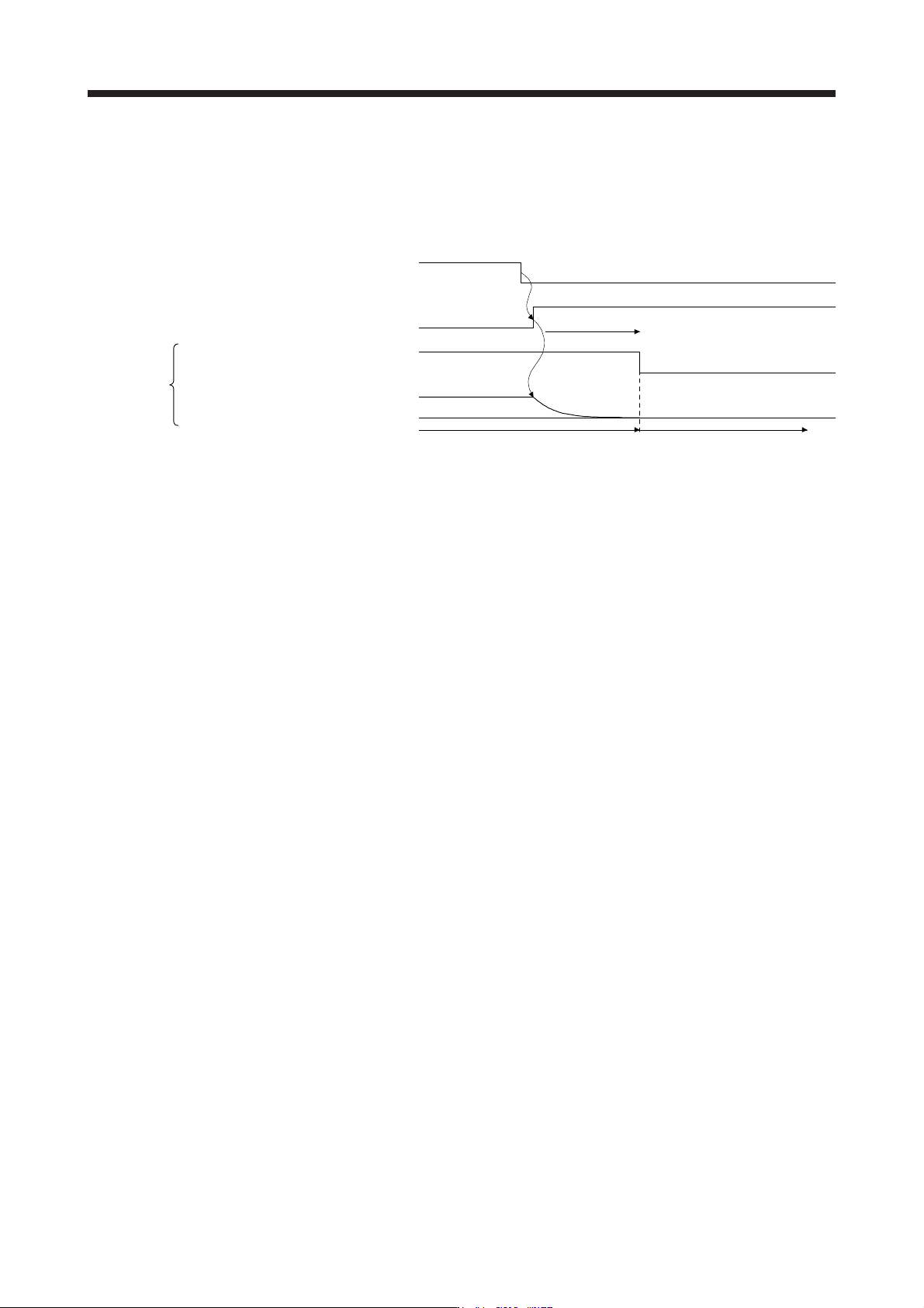
(2) Basic operation example
The switch status of STOA is input to SDI2A+ of MR-J3-D05, and then it will be input to STO1 and STO2
of the servo amplifier via SDO1A and SDO2A of MR-J3-D05.
The switch status of STOB is input to SDI2B+ of MR-J3-D05, and then it will be input to STO1 and STO2
of the servo amplifier via SDO1B and SDO2B of MR-J3-D05.
A
-axis shutdown 1 and
2
B-axis shutdown 1 and 2
STO1, STO2
Stop
Operation
Energizing (close)
Shut-off (open)
EM2 input
STO shut-off
Normal (close)
Shut-off (open)
0 r/min
Servo motor drivable
Servo motor speed
Servo amplifier
Shut off delay
STO status