sh030106u.pdf - 第462页
13. USIN G STO FUNCTI ON 13 - 9 (2) Basic o peration exam ple The switch s tatus of STO A is input t o SDI2 A+ of MR- J3-D05, and the n it wi ll be in put to STO 1 an d STO2 of the servo am plifier v ia SDO 1A and SDO 2A…
13. USING STO FUNCTION
13 - 8
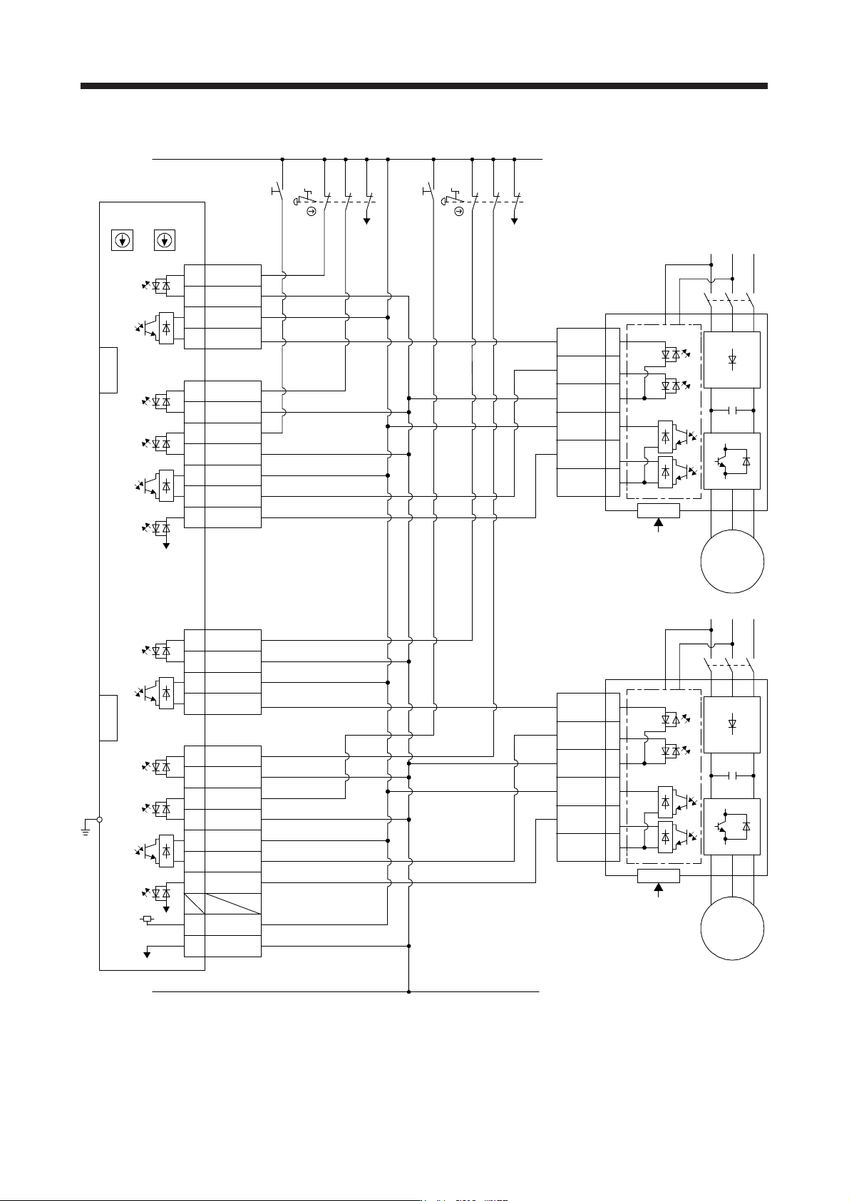
(1) Connection example
STO1
4
5
3
6
7
8
CN3
EM2 (B-axis)
CN8
SDO1A+4A
4B SDO1A-
SDI1A+1A
1B SDI1A-
SDI2A+
SRESA+
SDO2A+
TOFA
3A
3B
1A
1B
6A
6B
8A
SDI2A-
SDO2A-
SRESA-
CN9
CN10
STO1
TOFB2
TOFCOM
STO2
STOCOM
TOFB1
Servo amplifier
SW1
FG
4
5
3
6
7
8
CN3
EM2 (A-axis)
CN8
TOFB2
TOFCOM
STO2
STOCOM
TOFB1
Servo amplifier
SDO1B+3A
3B SDO1B-
SDI1B+2A
2B SDI1B-
SDI2B+
SRESB+
SDO2B+
TOFB
4A
4B
2A
2B
5A
5B
8B
+24V7A
0V7B
SDI2B-
SDO2B-
SRESB-
CN9
CN10
SW2
MR-J3-D05
(Note 1) (Note 1)
(Note 2) (Note 2)
S1
24 V
0 V
RESA
STOA
S3
RESB
STOB
MC
M
Servo motor
MC
M
Servo motor
Control circuit
Control circuit
S4
S2
CN8A
CN8B
EM2
(A-axis)
EM2
(B-axis)
Note 1. Set the delay time of STO output with SW1 and SW2. These switches are located in a recessed area to prevent accidental
settin
g
chan
g
es.
2. To release the STO state
(
base circuit shut-off
)
, turn RESA and RESB on and turn them off.
13. USING STO FUNCTION
13 - 9
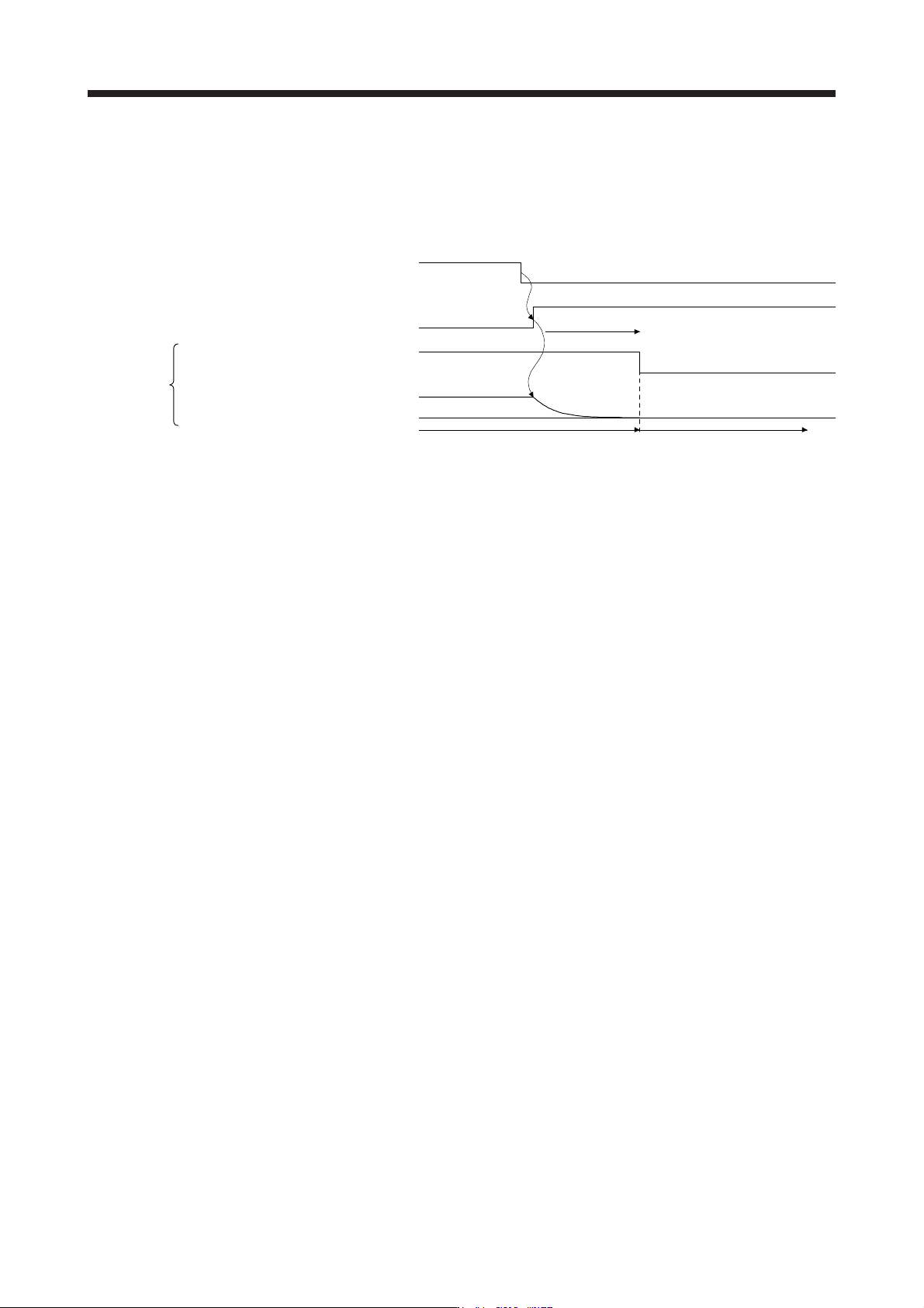
(2) Basic operation example
The switch status of STOA is input to SDI2A+ of MR-J3-D05, and then it will be input to STO1 and STO2
of the servo amplifier via SDO1A and SDO2A of MR-J3-D05.
The switch status of STOB is input to SDI2B+ of MR-J3-D05, and then it will be input to STO1 and STO2
of the servo amplifier via SDO1B and SDO2B of MR-J3-D05.
A
-axis shutdown 1 and
2
B-axis shutdown 1 and 2
STO1, STO2
Stop
Operation
Energizing (close)
Shut-off (open)
EM2 input
STO shut-off
Normal (close)
Shut-off (open)
0 r/min
Servo motor drivable
Servo motor speed
Servo amplifier
Shut off delay
STO status
13. USING STO FUNCTION
13 - 10
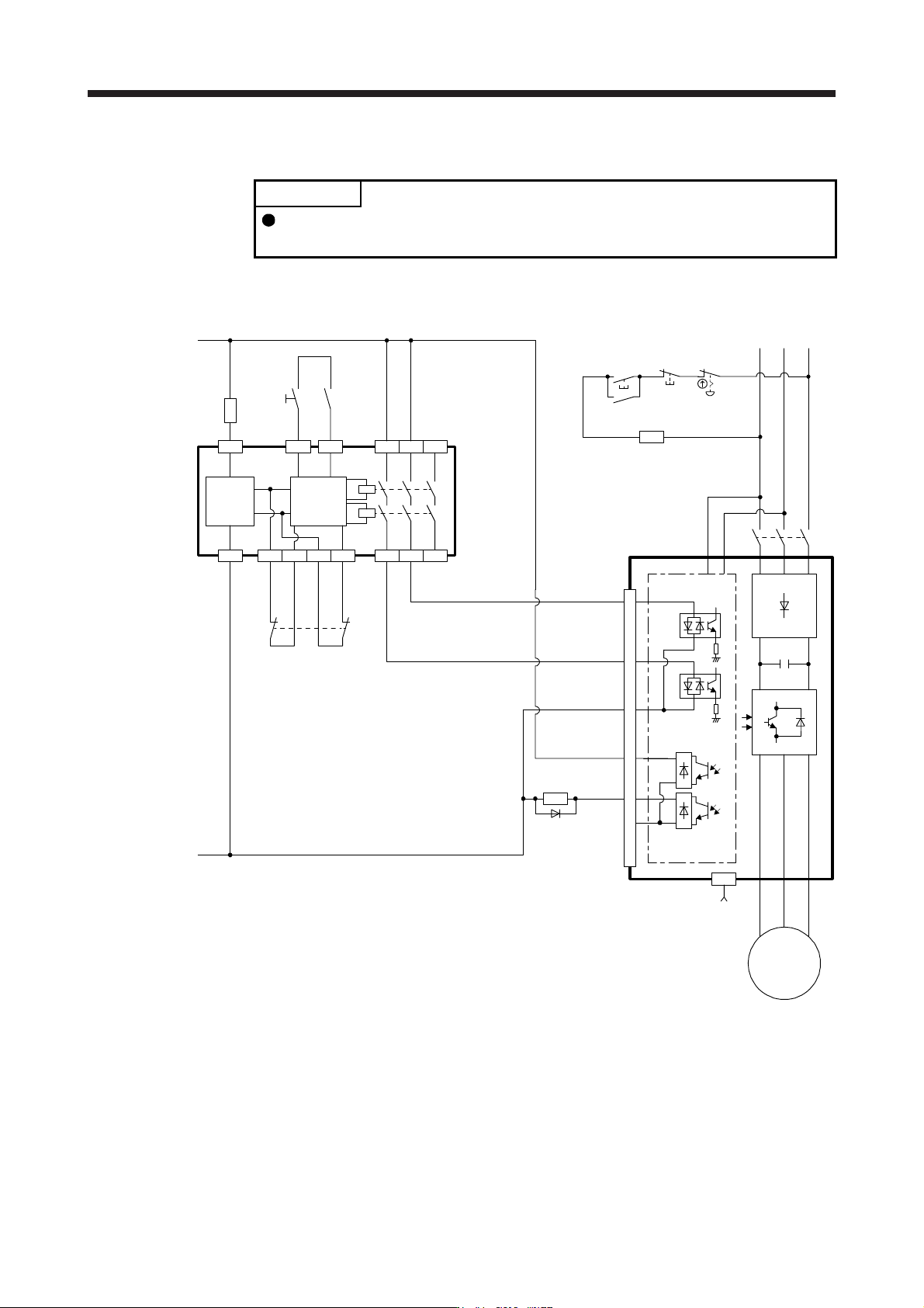
13.3.3 External I/O signal connection example using an external safety relay unit
POINT
This connection is for source interface. For the other I/O signals, refer to the
connection examples in section 3.2.2.
This connection example complies with the requirement of ISO/EN ISO 13849-1:2015 Category 3 PL d.
For details, refer to the safety relay module user’s manual.
Safety relay module
MELSEC
(QS90SR2S)
Fuse
24 V
0 V
S2
S1 or
EMG
(Note)
K3
Control
circuit
Power
supply
S1: STO shut-off switch (STO switch)
S2: Start switch (STO release switch)
S3: On switch
S4: Off switch
KM1: Magnetic contactor
K3: Safety relay
EMG: Emergency stop switch
+24V XS0 XS1 Z00 Z10 Z20
X0
COM0
24G X1
COM1
Z01 Z11 Z21
K3
CN8
KM1
CN3
20
EM1
or
EM2
Control circuit
Servo amplifier
STO1
TOFB1
TOFCOM
TOFB2
STO2
STOCOM
M
Servo motor
KM1
KM1
EMGS4
S3
Note. To enable the STO function of the servo amplifier by using "Emergency switching off", change S1 to EMG. The stop category at
this time is "0". If STO is turned off while the servo motor is rotatin
g
, [AL. 63 STO timin
g
error] will occur.