sh030106u.pdf - 第472页
14. USIN G A LINEAR SER VO MOTOR 14 - 5 (3) When usi ng A/ B/Z-phase different ial ou tput l inear enc oder w ith M R-J4-_B_- RJ The conf iguration d iagram is an ex ample of MR-J4- 20B-RJ . When u s ing the ot her serv …
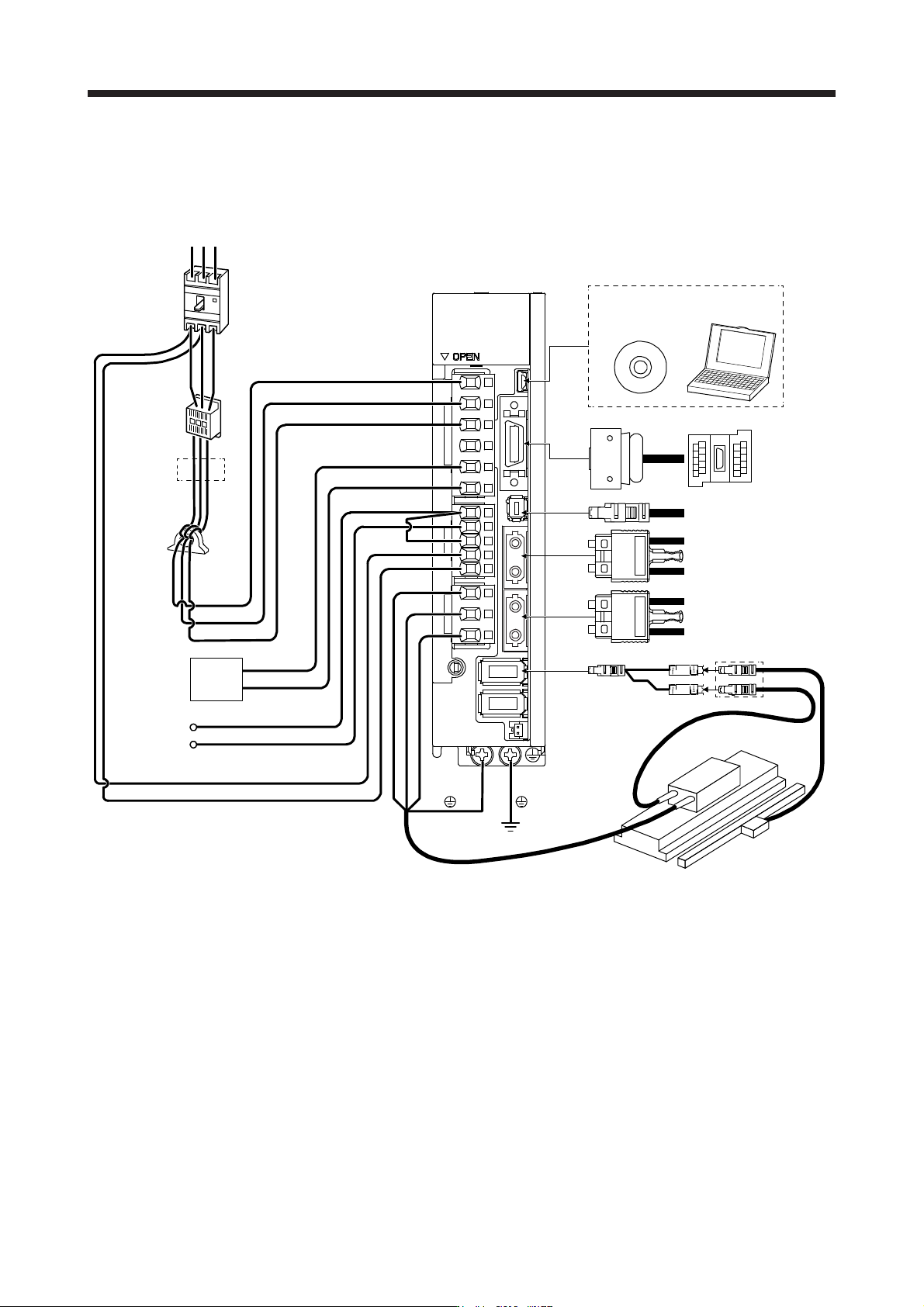
14. USING A LINEAR SERVO MOTOR
14 - 4
(2) When using serial linear encoder with MR-J4-_B_-RJ
The configuration diagram is an example of MR-J4-20B-RJ. When using the other servo amplifiers, the
configuration will be the same as rotary servo motors except for connections of linear servo motors and
linear encoders. Refer to section 1.8 depending on servo amplifiers you use.
Line noise
filter
(FR-BSF01)
CN5
Regenerative
option
P+
C
L11
L21
P3
P4
Personal
computer
MR Configurator2
CN3
CN8
CN1A
CN1B
CN2
W
V
U
L1
L2
L3
(Note 3)
Magnetic
contactor
(MC)
(Note 1)
Power factor
improving DC
reactor
(FR-HEL)
Molded-case
circuit breaker
(MCCB)
Junction
terminal
block
Safety relay or
MR-J3-D05 safety
logic unit
Servo system controller
or previous servo
amplifier CN1B
Next servo amplifier
CN1A or cap
(Note 2)
Power
supply
RS T
(Note 4)
Serial linear encoder
Linear servo motor
Encoder
cable
SCALE
THM
D
(Note 5)
(Note 6)
Thermistor
Note 1. The power factor improving AC reactor can also be used. In this case, the power factor improving DC reactor cannot be used.
When not usin
g
the power factor improvin
g
DC reactor, short P3 and P4.
2.
A
1-phase 200 V AC to 240 V AC power supply may be used with the servo amplifier of MR-J4-200B-RJ or less. For 1-phase
200 V AC to 240 V AC, connect the power supply to L1 and L3. Leave L2 open. For power supply specifications, refer to
section 1.3.
3. Depending on the main circuit voltage and operation pattern, bus voltage decreases, and that may cause the forced stop
deceleration to shift to the dynamic brake deceleration. When dynamic brake deceleration is not required, slow the time to turn
off the ma
g
netic contactor.
4. For the branch cable, use the MR-J4THCBL03M
(
optional
)
.
5.
A
lwa
y
s connect between P+ and D terminals. When usin
g
the re
g
enerative option, refer to section 11.2.
6. Connect the thermistor to THM of branch cable and connect the encoder cable to SCALE correctly. Incorrect setting will trigger
[AL. 16].
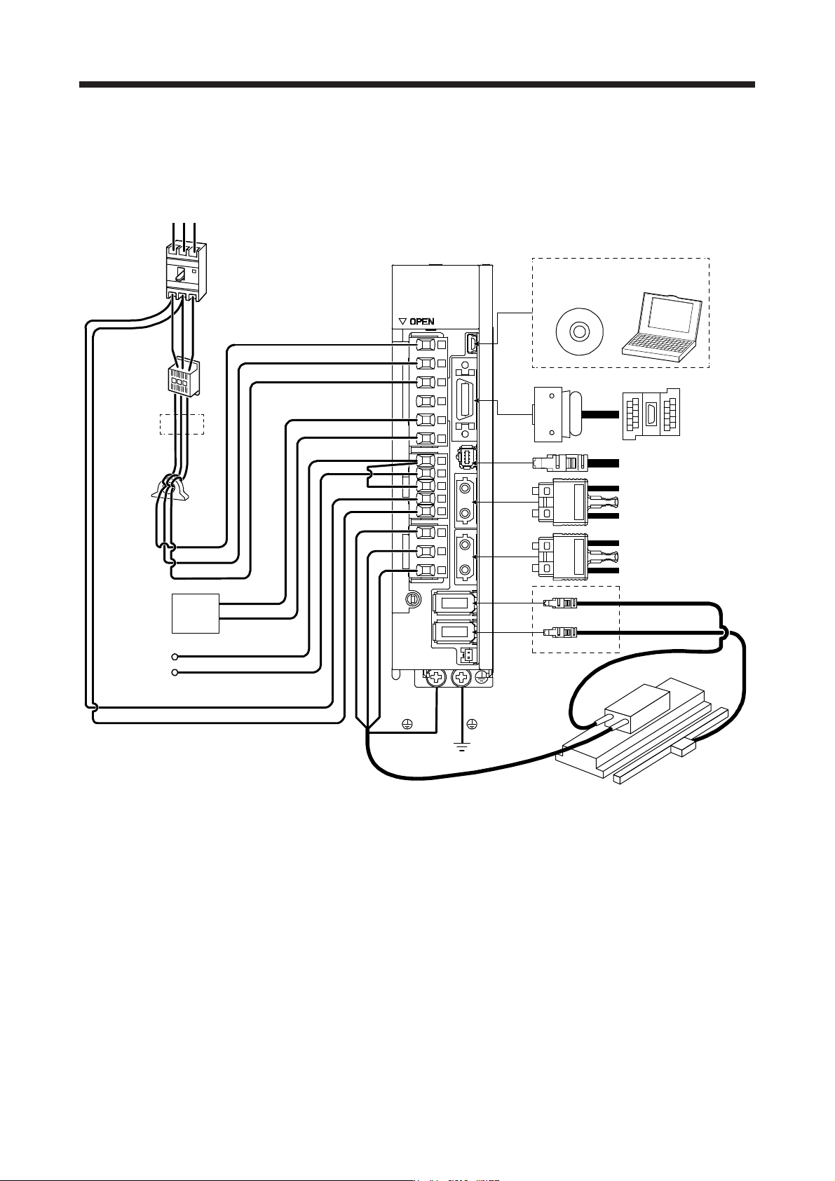
14. USING A LINEAR SERVO MOTOR
14 - 5
(3) When using A/B/Z-phase differential output linear encoder with MR-J4-_B_-RJ
The configuration diagram is an example of MR-J4-20B-RJ. When using the other servo amplifiers, the
configuration will be the same as rotary servo motors except for connections of linear servo motors and
linear encoders. Refer to section 1.8 depending on servo amplifiers you use.
CN5
P+
C
L11
L21
P3
P4
MR Configurator2
CN3
CN8
CN1A
CN1B
CN2
W
V
U
L1
L2
L3
RS T
CN2L
Line noise
filter
(FR-BSF01)
Regenerative
option
Personal
computer
(Note 3)
Magnetic
contactor
(MC)
(Note 1)
Power factor
improving DC
reactor
(FR-HEL)
Molded-case
circuit breaker
(MCCB)
Junction
terminal
block
Safety relay or
MR-J3-D05 safety
logic unit
Servo system controller
or previous servo
amplifier CN1B
Next servo amplifier
CN1A or cap
(Note 2)
Power
supply
A/B/Z-phase
differential output
linear encoder
Linear servo motor
Encoder
cable
D
(Note 4)
Thermistor
(Note 5)
Note 1. The power factor improving AC reactor can also be used. In this case, the power factor improving DC reactor cannot be used.
When not usin
g
the power factor improvin
g
DC reactor, short P3 and P4.
2.
A
1-phase 200 V AC to 240 V AC power supply may be used with the servo amplifier of MR-J4-200B-RJ or less. For 1-phase
200 V AC to 240 V AC, connect the power supply to L1 and L3. Leave L2 open. For the power supply specifications, refer to
section 1.3.
3. Depending on the main circuit voltage and operation pattern, bus voltage decreases, and that may cause the forced stop
deceleration to shift to the dynamic brake deceleration. When dynamic brake deceleration is not required, slow the time to turn
off the ma
g
netic contactor.
4.
A
lwa
y
s connect between P+ and D terminals. When usin
g
the re
g
enerative option, refer to section 11.2.
5. Connect the thermistor to CN2 of servo amplifier and connect the encoder cable to CN2L correctly. Incorrect setting will trigger
[AL. 16].
14. USING A LINEAR SERVO MOTOR
14 - 6
14.2 Signals and wiring
WARNING
Any person who is involved in wiring should be fully competent to do the work.
Before wiring, turn off the power and wait for 15 minutes or more until the charge
lamp turns off. Then, confirm that the voltage between P+ and N- is safe with a
voltage tester and others. Otherwise, an electric shock may occur. In addition,
when confirming whether the charge lamp is off or not, always confirm it from the
front of the servo amplifier.
Ground the servo amplifier and the linear servo motor securely.
Do not attempt to wire the servo amplifier and the linear servo motor until they
have been installed. Otherwise, it may cause an electric shock.
The cables should not be damaged, stressed, loaded, or pinched. Otherwise, it
may cause an electric shock.
To avoid an electric shock, insulate the connections of the power supply terminals.
CAUTION
Wire the equipment correctly and securely. Otherwise, the linear servo motor may
operate unexpectedly, resulting in injury.
Connect cables to the correct terminals. Otherwise, a burst, damage, etc. may
occur.
Ensure that polarity (+/-) is correct. Otherwise, a burst, damage, etc. may occur.
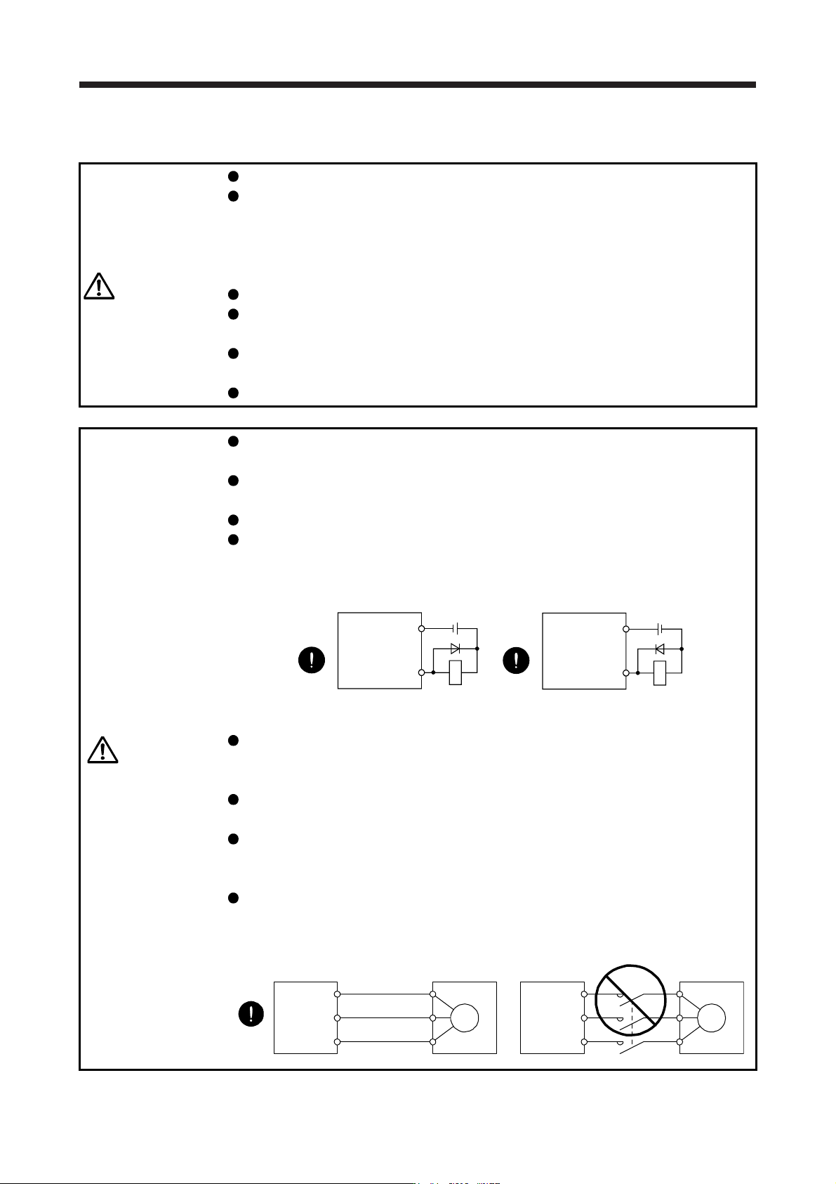
The surge absorbing diode installed to the DC relay for control output should be
fitted in the specified direction. Otherwise, the emergency stop and other
protective circuits may not operate.
DOCOM
24 V DC
Servo amplifier
RA
For sink output interface
Control output
signal
DOCOM
Control output
signal
24 V DC
Servo amplifier
RA
For source output interface
Use a noise filter, etc. to minimize the influence of electromagnetic interference.
Electromagnetic interference may be given to the electronic equipment used near
the servo amplifier.
Do not install a power capacitor, surge killer or radio noise filter (optional FR-BIF(-
H)) with the power wire of the linear servo motor.
When using the regenerative resistor, switch power off with the alarm signal.
Otherwise, a transistor fault or the like may overheat the regenerative resistor,
causing a fire.
Connect the servo amplifier power output (U/V/W) to the linear servo motor power
input (U/V/W) directly. Do not let a magnetic contactor, etc. intervene. Otherwise,
it may cause a malfunction.
Servo amplifier Servo amplifier
Linear servo
motor
Linear servo
motor
U
M
V
W
U
V
W
U
M
V
W
U
V
W