sh030106u.pdf - 第475页
14. USIN G A LINEAR SER VO MOTOR 14 - 8 14.3 Oper ation and funct ions 14.3.1 Star tup POINT When usi ng the linear ser vo mot or, set [ Pr. PA01] to " _ _ 4 _". (1) Startup proc edure Sta rt up the linea r ser…
14. USING A LINEAR SERVO MOTOR
14 - 7
CAUTION
Before wiring, switch operation, etc., eliminate static electricity. Otherwise, it may
cause a malfunction.
Connecting a linear servo motor for different axis to the U, V, W, or CN2 may
cause a malfunction.
Do not modify the equipment.
The cables such as power wires deriving from the primary side cannot stand the
long-term bending action. Avoid the bending action by fixing the cables to the
moving part, etc. Also, use the cable that stands the long-term bending action for
the wiring to the servo amplifier.
This chapter does not describe the following items. For details of the items, refer to each section of the
detailed description field.
Item Detailed explanations
Input power supply circuit Section 3.1
Explanation of power supply system Section 3.3
Signal (device) explanations Section 3.5
Alarm occurrence timing chart Section 3.7
Interfaces Section 3.8
SSCNET III cable connection Section 3.9
Grounding Section 3.11
Switch setting and display of the servo
amplifier
Section 4.3
14. USING A LINEAR SERVO MOTOR
14 - 8
14.3 Operation and functions
14.3.1 Startup
POINT
When using the linear servo motor, set [Pr. PA01] to "_ _ 4 _".
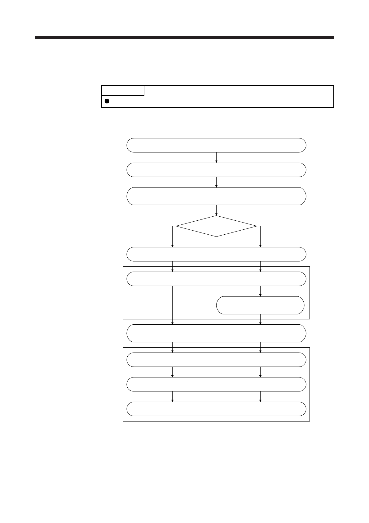
(1) Startup procedure
Start up the linear servo system in the following procedure.
Set the linear servo motor series and linear servo motor type.
(Refer to (2) in this section.)
(Note)
Set the linear encoder direction and the linear servo motor direction.
(Refer to (3) in this section.)
(Note)
Set the linear encoder resolution. (Refer to (4) in this section.)
Change the setting to disable the
magnetic pole detection.
(Refer to (3) of section 14.3.2.)
What is the type of the
linear encoder?
Installation and wiring
(Note)
Perform the magnetic pole detection. (Refer to (3) of section 14.3.2.)
(Note)
Positioning operation check using the test operation mode
(Refer to section 14.3.4.)
Positioning operation check using the controller (Refer to section 14.3.5.)
Home position return operation (Refer to section 14.3.3.)
Positioning operation
Incremental linear encoder Absolute position linear encoder
Note. Use MR Confi
g
urator2.
(2) Set the linear servo motor series and linear servo motor type.
To use the linear servo motor, set the linear servo motor series and linear servo motor type with [Pr.
PA17 Servo motor series setting] and [Pr. PA18 Servo motor type setting]. (Refer to section 5.2.1.)
14. USING A LINEAR SERVO MOTOR
14 - 9
(3) Settings of the linear encoder direction and the linear servo motor direction
POINT
If an incorrect value is set for [Pr. PC27], the servo motor may not operate
properly, or [AL. 50] or [AL. 51] may occur at the positioning operation or the
magnetic pole detection.
Set the first digit of [Pr. PC27] (Encoder pulse count polarity selection) so that the positive direction of
the linear servo motor matches with the increasing direction of the linear encoder feedback.
[Pr. PC27]
Encoder pulse count polarity selection
0: Linear servo motor positive direction and linear encoder increasing direction
1: Linear servo motor positive direction and linear encoder decreasing direction
(a) Parameter setting method
1) Confirm the positive direction of the linear servo motor. [Pr. PA14] determines the relation of the
travel direction of the linear servo motor under commands as shown below.
[Pr. PA14] setting
Travel direction of linear servo motor
Address increasing
command
Address decreasing
command
0 Positive direction Negative direction
1 Negative direction Positive direction
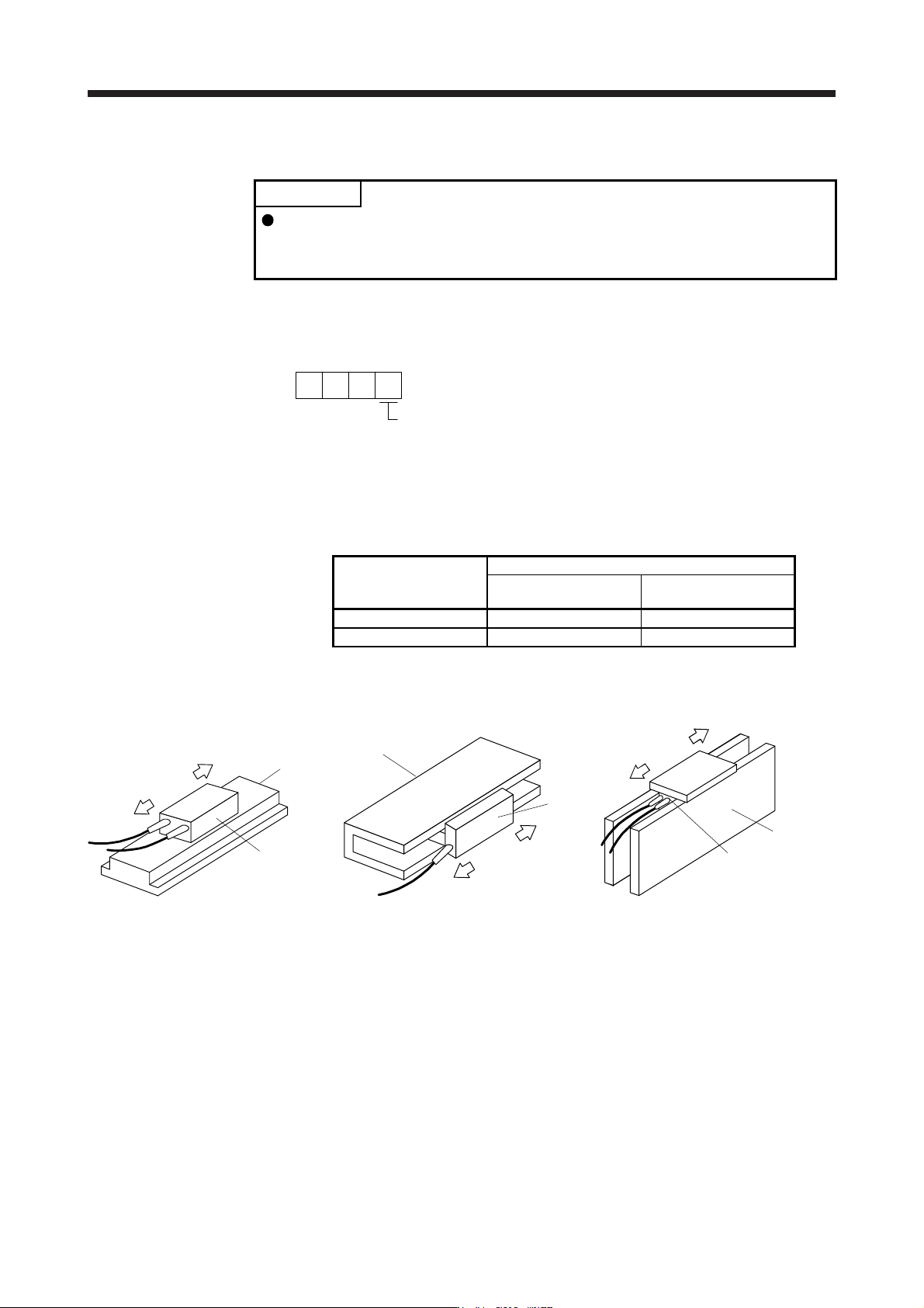
The positive/negative directions of the linear servo motor are as follows.
Secondary
side
Primary side
Positive
direction
Ne
g
ative
direction
LM-H3 and LM-F series
Negative direction
Positive
direction
Secondary side
Primary
side
LM-U2 series
Negative
direction
Positive
direction
Table
Primary
side
Secondary
side
LM-K2 series
2) Confirm the increasing direction of the linear encoder.
3) If the positive direction of the linear servo motor matches with the increasing direction of the linear
encoder, set [Pr. PC27] to "_ _ _ 0". If the positive direction of the linear servo motor does not
match with the increasing direction of the linear encoder, set [Pr. PC27] to "_ _ _ 1".