sh030106u.pdf - 第477页
14. USIN G A LINEAR SER VO MOTOR 14 - 10 (b) Confir mation met hod Confirm th e positiv e direc tion of the l inear ser vo motor and th e increas ing direct ion of t he linear encoder in the fol lowing proc edure. 1) In …
14. USING A LINEAR SERVO MOTOR
14 - 9
(3) Settings of the linear encoder direction and the linear servo motor direction
POINT
If an incorrect value is set for [Pr. PC27], the servo motor may not operate
properly, or [AL. 50] or [AL. 51] may occur at the positioning operation or the
magnetic pole detection.
Set the first digit of [Pr. PC27] (Encoder pulse count polarity selection) so that the positive direction of
the linear servo motor matches with the increasing direction of the linear encoder feedback.
[Pr. PC27]
Encoder pulse count polarity selection
0: Linear servo motor positive direction and linear encoder increasing direction
1: Linear servo motor positive direction and linear encoder decreasing direction
(a) Parameter setting method
1) Confirm the positive direction of the linear servo motor. [Pr. PA14] determines the relation of the
travel direction of the linear servo motor under commands as shown below.
[Pr. PA14] setting
Travel direction of linear servo motor
Address increasing
command
Address decreasing
command
0 Positive direction Negative direction
1 Negative direction Positive direction
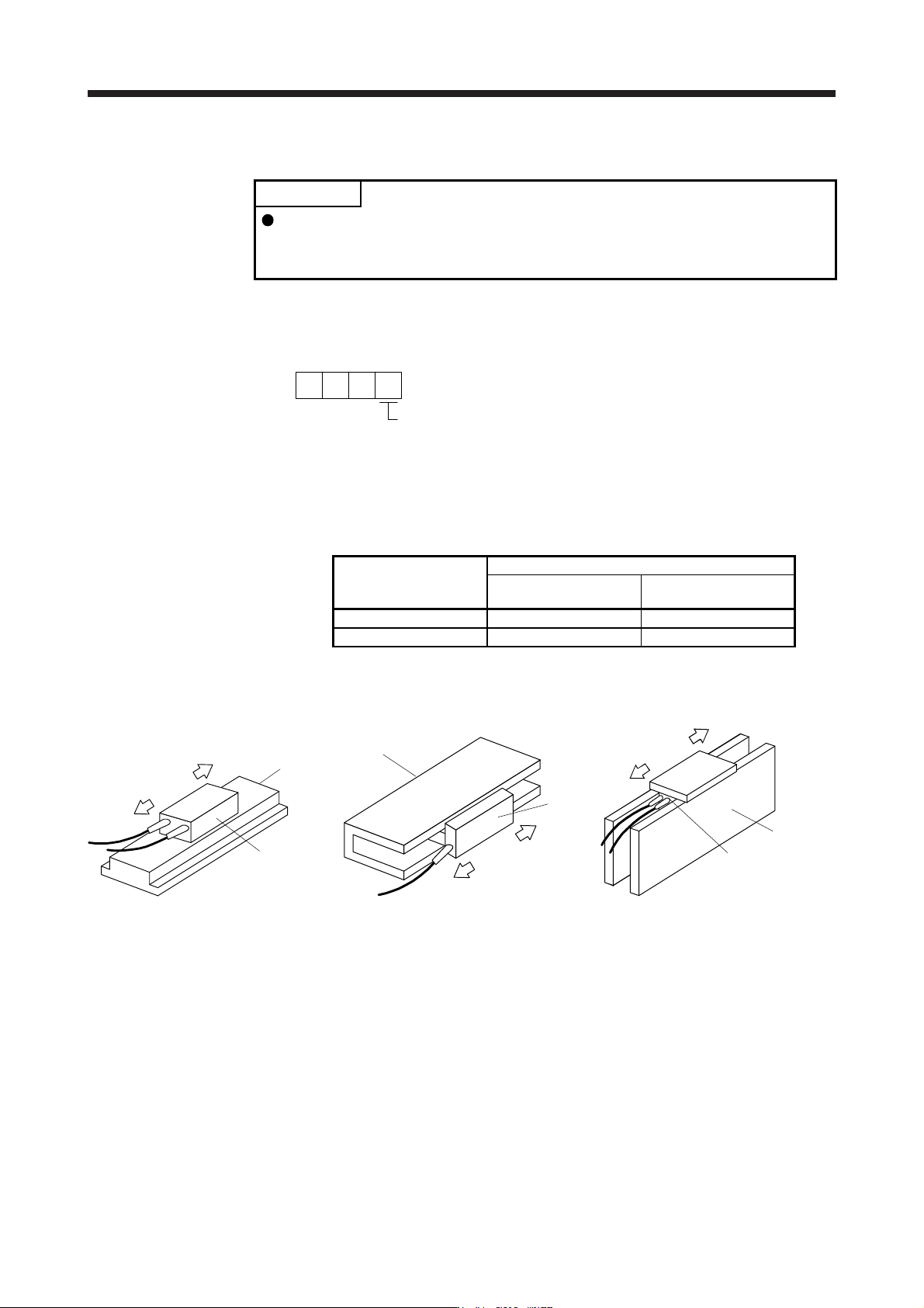
The positive/negative directions of the linear servo motor are as follows.
Secondary
side
Primary side
Positive
direction
Ne
g
ative
direction
LM-H3 and LM-F series
Negative direction
Positive
direction
Secondary side
Primary
side
LM-U2 series
Negative
direction
Positive
direction
Table
Primary
side
Secondary
side
LM-K2 series
2) Confirm the increasing direction of the linear encoder.
3) If the positive direction of the linear servo motor matches with the increasing direction of the linear
encoder, set [Pr. PC27] to "_ _ _ 0". If the positive direction of the linear servo motor does not
match with the increasing direction of the linear encoder, set [Pr. PC27] to "_ _ _ 1".
14. USING A LINEAR SERVO MOTOR
14 - 10
(b) Confirmation method
Confirm the positive direction of the linear servo motor and the increasing direction of the linear
encoder in the following procedure.
1) In servo-off status, move the linear servo motor in the positive direction manually.
2) Confirm the motor speed (in the positive and negative directions) at that time with MR
Configurator2.
3) When [Pr. PC27] is set to "_ _ _ 0" and the positive direction of the linear servo motor matches
with the increasing direction of the linear encoder, if the linear servo motor operates in the
positive direction, the motor speed will be a positive value. If the positive direction of the linear
servo motor does not match with the increasing direction of the linear encoder, the motor speed
will be a negative value. When [Pr. PC27] is set to "_ _ _ 1" and the positive direction of the linear
servo motor matches with the increasing direction of the linear encoder, if the linear servo motor
operates in the positive direction, the motor speed will be a negative value.
(4) Linear encoder resolution setting
POINT
To enable the parameter value, cycle the power after setting.
If an incorrect value is set for [Pr. PL02] or [Pr. PL03], the linear servo motor
may not operate properly, or [AL. 27] or [AL. 42] may occur at the positioning
operation or the magnetic pole detection.
Set the ratio of the electronic gear to the linear encoder resolution with [Pr. PL02 Linear encoder
resolution - Numerator] and [Pr. PL03 Linear encoder resolution - Denominator].
(a) Parameter setting
Set the values that apply to the following equation.
[Pr. PL02 Linear encoder resolution - Numerator]
[Pr. PL03 Linear encoder resolution - Denominator]
= Linear encoder resolution [µm]
(b) Parameter setting example
When the linear encoder resolution is 0.5 µm
[Pr. PL02]
[Pr. PL03]
= Linear encoder resolution = 0.5 µm =
2
1
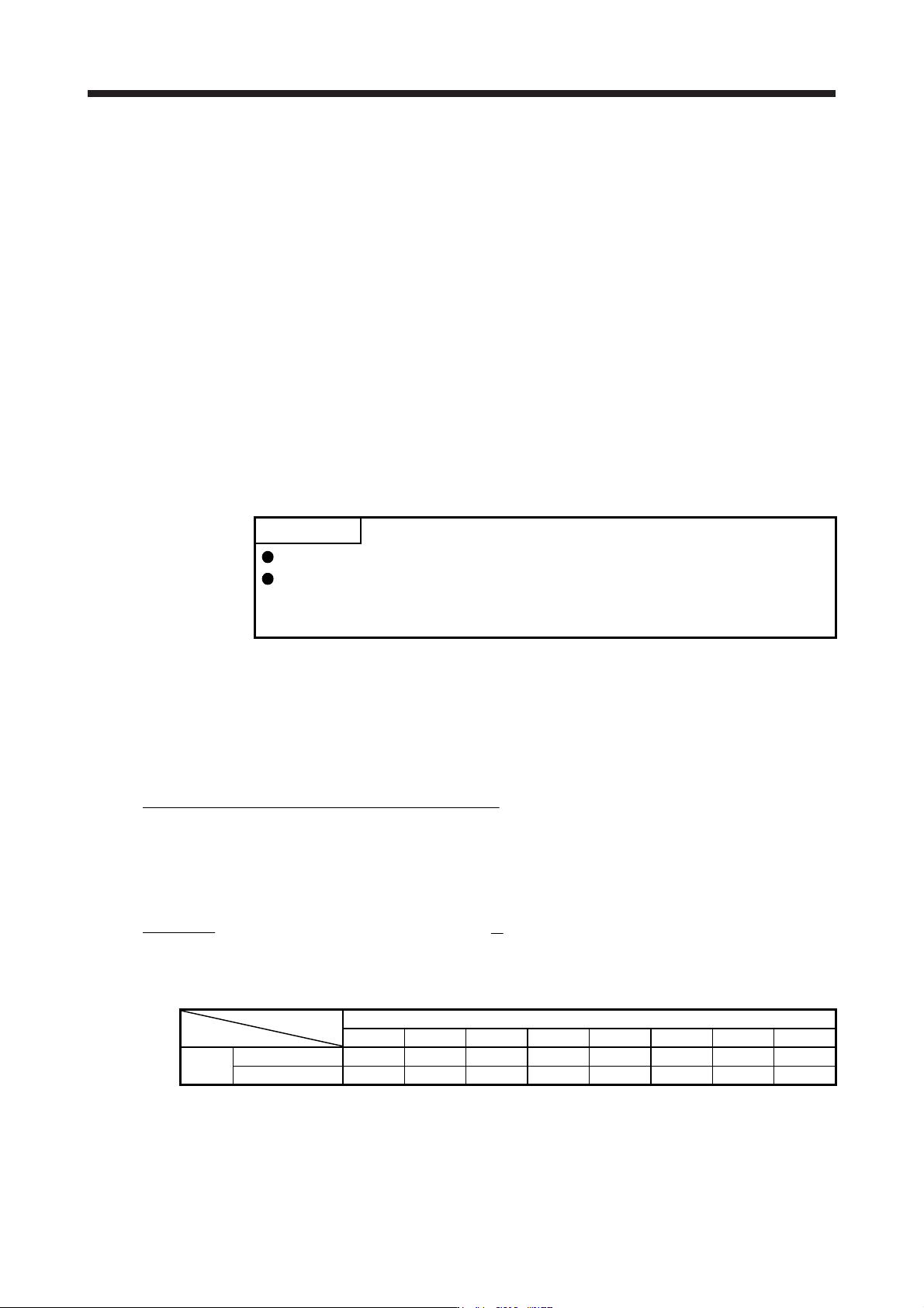
The following shows the simplified chart for the setting values of [Pr. PL02] and [Pr. PL03].
Linear encoder resolution [µm]
0.01 0.02 0.05 0.1 0.2 0.5 1.0 2.0
Setting
value
[Pr. PL02] 1 1 1 1 1 1 1 2
[Pr. PL03] 100 50 20 10 5 2 1 1

14. USING A LINEAR SERVO MOTOR
14 - 11
14.3.2 Magnetic pole detection
POINT
Set [Pr. PE47 Torque offset] to "0 (initial value)" before executing the magnetic
pole detection.
Before the positioning operation of the linear servo motor, make sure to perform the magnetic pole detection.
When [Pr. PL01] is set to the initial value, perform the magnetic pole detection only at the first servo-on after
the power is turned on.
The magnetic pole detection includes the following two methods. Each method has advantages and
disadvantages. Select a magnetic pole detection method suitable for your usage.
The position detection method is selected in the initial setting.
Magnetic pole detection Advantage Disadvantage
Position detection method
1. The magnetic pole detection has a
high degree of accuracy.
2. The adjustment procedure at the
magnetic pole detection is simple.
1. The travel distance at the
magnetic pole detection is large.
2. For equipment with small friction,
the initial magnetic pole detection
error may occur.
Minute position detection method
1. The travel distance at the
magnetic pole detection is small.
2. Even for equipment with small
friction, the magnetic pole
detection is available.
1. The adjustment procedure at the
magnetic pole detection is
complex.
2. If a disturbance occurs during the
magnetic pole detection, [AL. 27
Initial magnetic pole detection
error] may occur.