sh030106u.pdf - 第492页
14. USIN G A LINEAR SER VO MOTOR 14 - 25 (b) O utput sign al (DO) forced output Output s ignals c an be sw itched on/off forc ibly i ndepen dently of the s ervo stat us. This func tion is used for outp ut signa l wiring …
14. USING A LINEAR SERVO MOTOR
14 - 24
14.3.4 Test operation mode in MR Configurator2
CAUTION
The test operation mode is designed for checking servo operation. It is not for
checking machine operation. Do not use this mode with the machine. Always use
the linear servo motor alone.
If the servo motor operates abnormally, use EM2 (Forced stop 2) to stop it.
POINT
The content described in this section indicates the environment where the servo
amplifier and a personal computer are directly connected.
When the test operation mode is selected with the test operation select switch
(SW2-1), the SSCNET III/H communication for the servo amplifier in the test
operation mode and the following servo amplifiers is blocked.
By using a personal computer and MR Configurator2, you can execute the positioning operation, the output
signal (DO) forced output, and the program operation without connecting the servo system controller.
(1) Test operation mode type
(a) Positioning operation
Positioning operation can be performed without using the servo system controller. Use this operation
with the forced stop reset. This operation may be used independently of whether the servo is on or
off and whether the servo system controller is connected or not.
Exercise control on the positioning operation screen of MR Configurator2.
1) Operation pattern
Item Initial value Setting range
Travel distance [pulse] 1048576 0 to 99999999
Speed [mm/s] 10 0 to Maximum speed
Acceleration/deceleration
time constant [ms]
1000 0 to 50000
Repeat pattern
Positive direction travel →
Negative direction travel
Positive direction travel →
Negative direction travel
Positive direction travel →
Positive direction travel
Negative direction travel →
Positive direction travel
Negative direction travel →
Negative direction travel
Dwell time [s] 2.0 01 to 50.0
Number of repeats [time] 1 1 to 9999
2) Operation method
Operation Screen control
Positive direction travel Click "Positive Direction Movement".
Negative direction travel Click "Reverse Direction Movement".
Pause Click "Pause".
Stop Click "Stop".
Forced stop Click "Forced stop".
14. USING A LINEAR SERVO MOTOR
14 - 25
(b) Output signal (DO) forced output
Output signals can be switched on/off forcibly independently of the servo status. This function is
used for output signal wiring check, etc. Exercise control on the DO forced output screen of MR
Configurator2.
(c) Program operation
Positioning operation can be performed in two or more operation patterns combined, without using
the servo system controller. Use this operation with the forced stop reset. This operation may be
used independently of whether the servo is on or off and whether the servo system controller is
connected or not.
Exercise control on the program operation screen of MR Configurator2. For details, refer to Help of
MR Configurator2.
Operation Screen control
Start Click "Operation start".
Pause Click "Pause".
Stop Click "Stop".
Forced stop Click "Forced stop".
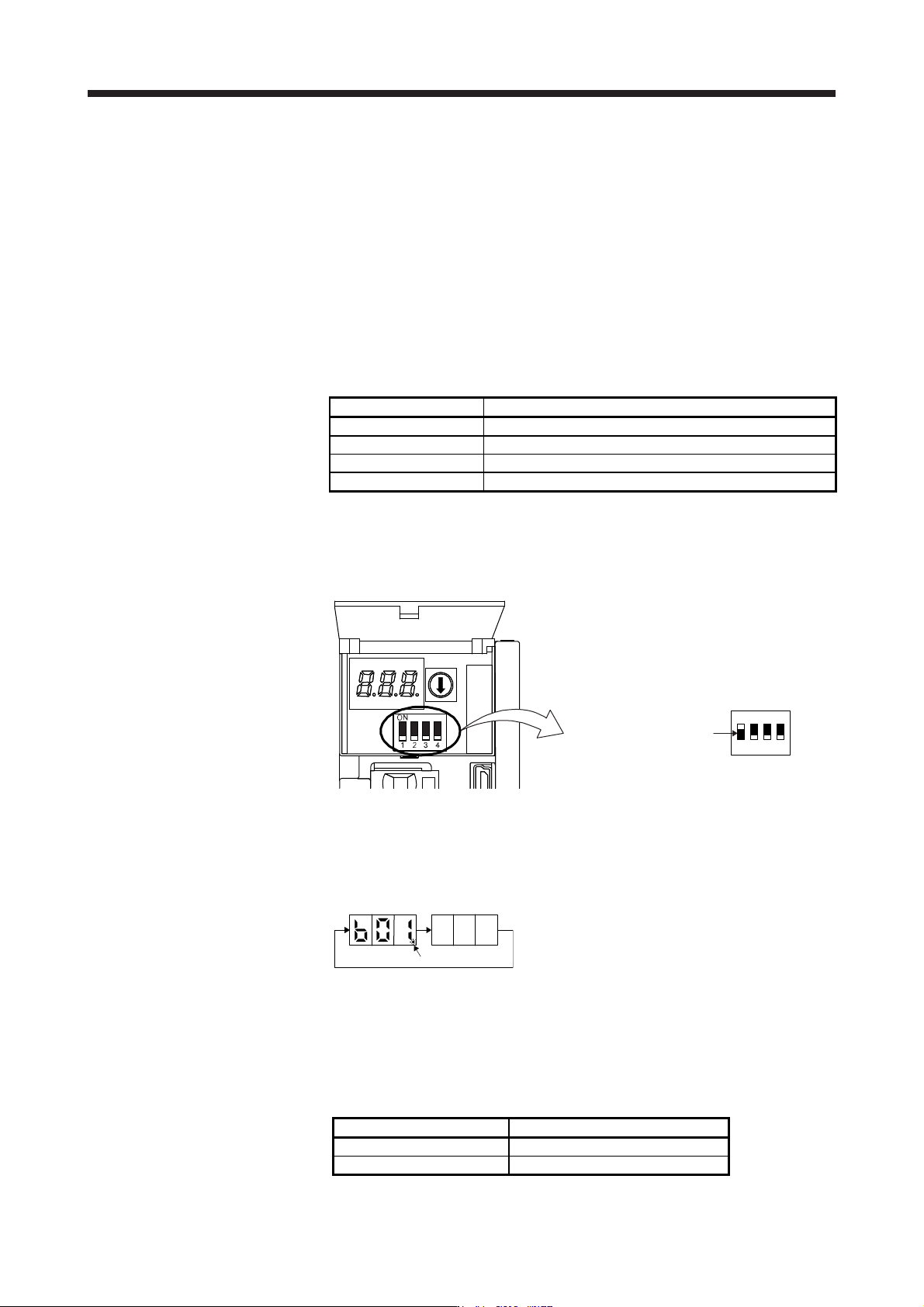
(2) Operation procedure
1) Turn off the power.
2) Turn "ON (up)" SW2-1.
Set SW2-1 to "ON (up)".
1
ON
2 3 4
Turning "ON (up)" SW2-1 during power-on will not enable the test operation mode.
3) Turn on the servo amplifier.
When initialization is over, the display shows the following screen.
After 1.6 s
After 0.2 s
Blinking
4) Start operation with the personal computer.
14.3.5 Operation from controller
The linear servo can be used with any of the following controllers.
Servo system controller Model
Motion controller R_MTCPU/Q17_DSCPU
Simple motion module RD77MS_/QD77MS_ /LD77MS_
14. USING A LINEAR SERVO MOTOR
14 - 26
(1) Operation method
For the system using the incremental linear encoder, the magnetic pole detection is automatically
performed at the first servo-on after the power-on. For this reason, when performing the positioning
operation, create the sequence which surely confirms the servo-on status as the inter lock condition of
the positioning command.
Also, some parameter settings and the home position return type differ according to the controller type.
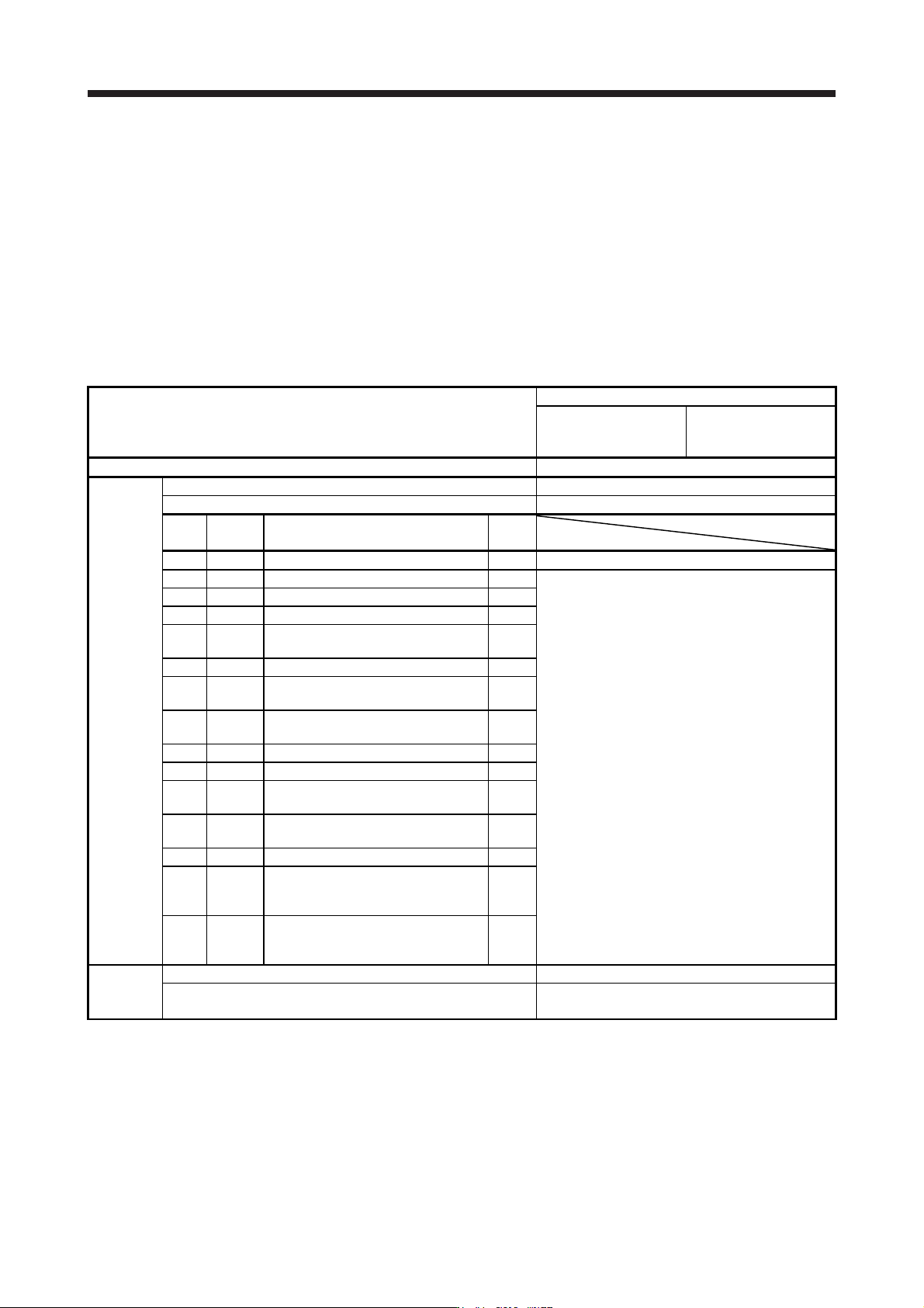
(2) Servo system controller setting
(a) Setting precautions
The following parameters will be enabled by cycling the servo amplifier power after the controller
writes the parameters to the servo amplifier.
Setting item
Set content
Motion controller
R_MTCPU/Q17_DSCPU
Simple motion module
RD77MS_/QD77MS_ /
LD77MS_
Command resolution Linear encoder resolution unit
Parameter
Servo amplifier setting MR-J4-B Linear
Motor setting Automatic setting
No.
(Note)
Symbol
Name
Initial
value
PA01 **STY Operation mode 1000h 1040h
PC01 ERZ Error excessive alarm level 0
Set the items as required.
PC03 *ENRS Encoder output pulse selection 0000h
PC27 **COP9 Function selection C-9 0000h
PL01 **LIT1
Linear servo motor/DD motor function
selection 1
0301h
PL02 **LIM Linear encoder resolution - Numerator 1000
PL03 **LID
Linear encoder resolution -
Denominator
1000
PL04 *LIT2
Linear servo motor/DD motor function
selection 2
0003h
PL05 LB1 Position deviation error detection level 0
PL06 LB2 Speed deviation error detection level 0
PL07 LB3
Torque/thrust deviation error detection
level
100
PL08 *LIT3
Linear servo motor/DD motor function
selection 3
0010h
PL09 LPWM Magnetic pole detection voltage level 30
PL17 LTSTS
Magnetic pole detection - Minute
position detection method - Function
selection
0000h
PL18 IDLV
Magnetic pole detection - Minute
position detection method -
Identification signal amplitude
0
Positioning
control
parameter
Unit setting mm
Number of pulses (AP)
Travel distance (AL)
Refer to (2) (b) in this section.
Note. The parameter whose symbol is preceded by * is enabled with the following conditions.
* : After setting the parameter, power off and on the servo amplifier or reset the controller.
**: After settin
g
the parameter, c
y
cle the power of the servo amplifier.