sh030106u.pdf - 第495页
14. USIN G A LINEAR SER VO MOTOR 14 - 28 (a) Posit ion deviati on err or detec tion Set [Pr. PL04] to " _ _ _ 1" to enabl e the p osition deviat ion er r or detec tion. [Pr. PL04] Position deviation error detec…
14. USING A LINEAR SERVO MOTOR
14 - 27
(b) Settings of the number of pulses (AP) and travel distance (AL)
AP
AL
Position feedback
[mm]
Command
[mm]
+
-
Speed feedback
[mm/s]
AL
AP
User
Controlle
r
Servo amplifier
Linear servo
motor
Linear encoder
Differ-
entiation
Calculate the number of pulses (AP) and travel distance (AL) of the linear encoder in the following
conditions.
When the linear encoder resolution is 0.05 µm
Number of pulses (AP) [pulse]
=
1
0.05
=
20
1
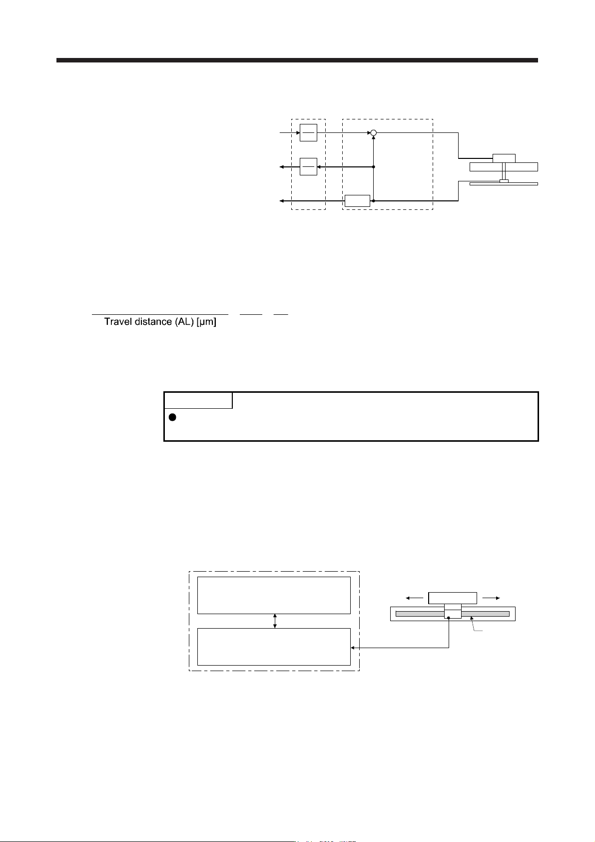
14.3.6 Function
(1) Linear servo control error detection function
POINT
For the linear servo control error detection function, the position and speed
deviation error detections are enabled by default. ([Pr. PL04]: _ _ _ 3)
If the linear servo control gets unstable for some reasons, the linear servo motor may not operate
properly. To detect this state and to stop operation, the linear servo control error detection function is
used as a protective function.
The linear servo control error detection function has three different detection methods: the position
deviation, speed deviation, and thrust deviation. An error is detected when each method is enabled with
[Pr. PL04 Linear servo motor/DD motor function selection 2]. The detection level can be changed with
[Pr. PL05], [Pr. PL06], and [Pr. PL07].
Servo amplifier internal value
1) Model feedback position [mm]
3) Model feedback speed [mm/s]
5) Command thrust [%]
Linear encoder
2) Feedback position [mm]
4) Feedback speed [mm/s]
6) Feedback thrust [%]
Servo amplifier
Linear servo motor
Linear encoder
Figure 14.1 Outline of linear servo control error detection function

14. USING A LINEAR SERVO MOTOR
14 - 28
(a) Position deviation error detection
Set [Pr. PL04] to "_ _ _ 1" to enable the position deviation error detection.
[Pr. PL04]
Position deviation error detection enabled
1
When you compare the model feedback position ( 1)) and the feedback position ( 2)) in figure 14.1, if
the deviation is more than the value of [Pr. PL05 Position deviation error detection level] (1 mm to
1000 mm), [AL. 42.1 Servo control error by position deviation] will occur and the linear servo motor
will stop. The initial value of this detection level is 50 mm. Replace the set value as required.
(b) Speed deviation error detection
Set [Pr. PL04] to "_ _ _ 2" to enable the speed deviation error detection.
[Pr. PL04]
Speed deviation error detection enable
d
2
When you compare the model feedback speed ( 3)) and the feedback speed ( 4)) in figure 14.1, if the
deviation is more than the value of [Pr. PL06 Speed deviation error detection level] (1 mm/s to 5000
mm/s), [AL. 42.2 Servo control error by speed deviation] will occur and the linear servo motor will
stop. The initial value of this detection level is 1000 mm/s. Replace the set value as required.
(c) Thrust deviation error detection level
Set [Pr. PL04] to "_ _ _ 4" to enable the thrust deviation error detection.
[Pr. PL04]
Thrust deviation error detection enabled
4
When you compare the command thrust ( 5)) and the feedback thrust ( 6)) in figure 14.1, if the
deviation is more than the value of [Pr. PL07 Torque/thrust deviation error detection level] (1% to
1000%), [AL. 42.3 Servo control error by torque/thrust deviation] will occur and the linear servo motor
will stop. The initial value of this detection level is 100%. Replace the set value as required.
(d) Detecting multiple deviation errors
When setting [Pr. PL04] as shown below, multiple deviation errors can be detected. For the error
detection methods, refer to (1) (a), (b), (c) in this section.
[Pr. PL04]
Position deviation
error detection
Setting
value
Speed deviation
error detection
Thrust deviation
error detection
1
5
6
7
3
2
4

14. USING A LINEAR SERVO MOTOR
14 - 29
(2) Auto tuning function
POINT
The auto tuning mode 1 may not be performed properly if the following
conditions are not satisfied.
Time to reach 2000 mm/s is the acceleration/deceleration time constant of 5 s
or less.
The linear servo motor speed is 150 mm/s or higher.
The load to mass of the linear servo motor primary-side ratio is 100 times or
less.
The acceleration/deceleration thrust is 10% or less of the continuous thrust.
The auto tuning function during the linear servo motor operation is the same as that of the rotary servo
motor. However, the calculation method of the load to motor mass ratio (J ratio) differs. The load to
motor mass ratio (J ratio) on the linear servo motor is calculated by dividing the load mass by the mass
of the linear servo motor primary side.
Example) Mass of linear servo motor primary side
Load mass (excluding the mass of the linear servo motor primary side)
Mass ratio
= 2 kg
= 4 kg
= 4/2 = 2 times
For the parameters set by the auto tuning function, refer to chapter 6.
(3) Machine analyzer function
POINT
Make sure to perform the machine analyzer function after the magnetic pole
detection. If the magnetic pole detection is not performed, the machine analyze
function may not operate properly.
The stop position at the completion of the machine analyzer function can be any
position.
14.3.7 Absolute position detection system
When the linear servo motor is used with the absolute position detection system, an absolute position linear
encoder is required. The linear encoder backs up the absolute position data. Therefore, the encoder battery
need not be installed to the servo amplifier. Additionally, [AL. 25 Absolute position erased], [AL. 92 Battery
cable disconnection warning], [AL. 9F Battery warning], and [AL. E3 Absolute position counter warning] are
not provided for the linear servo motor.